


Table of contents: Body geometry ↓ Measurement points ↓
Body geometry
Use rolling sensors to ensure correct wheel alignment (the rear wheels must be strictly in the track of the front wheels), - make sure that the sensors are installed correctly and that the lengths of the indicators are equal.
When using a tape measure (preferably metal) make sure that the measuring tape is not twisted or kinked.
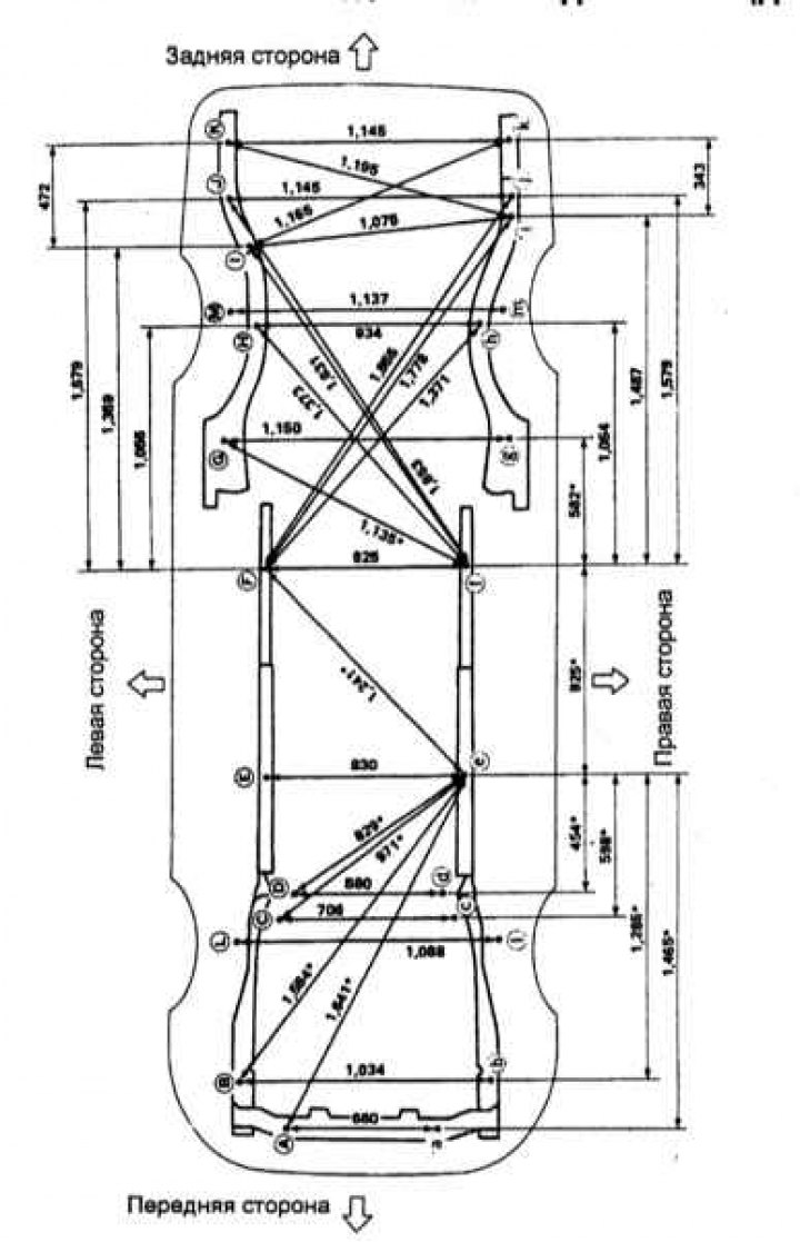
The presence of an asterisk (*) after the value at a measurement point indicates that the second measurement point is located symmetrically relative to the specified one.
The coordinates of the measurement points are distances measured in three main directions ("X", "Y", "Z").
Location of coordinate axes when measuring geometric parameters of a car body
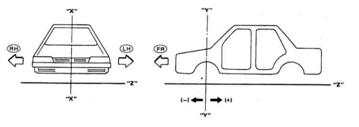
FR - Forward
LH - Left side
RH - Starboard
"X-X" - Diametrical plane of the car
"YY" - A vertical plane passing through the axle of the front wheels of a vehicle
"ZZ" - Main plane
Measurement points
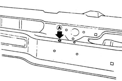
Mark at the center of the front edge of the engine compartment opening
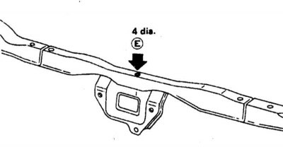
Upper central radiator support
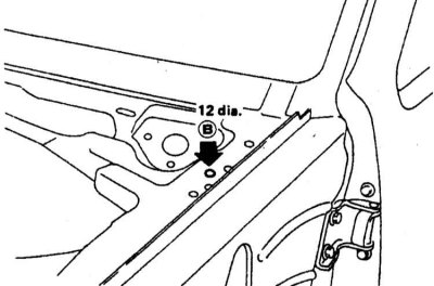
Left rear corner of engine compartment opening
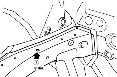
Front spar

Strut support and front side member
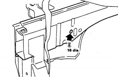
Front spar
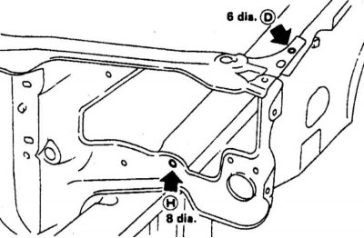
Upper radiator support
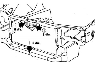
Front panel
Engine compartment geometry for 1993 and 1994 models.
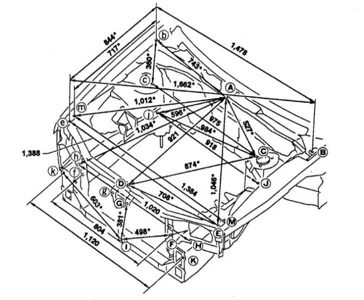
Radiator base support (front part) and front suspension (located below the previous ones) and the front spar (closer to the center)
Rear and center elements
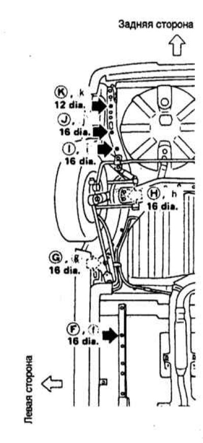
Engine compartment geometry of 1995 models.
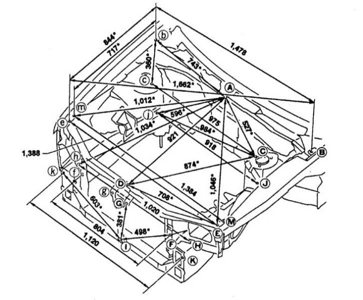
Measurement points
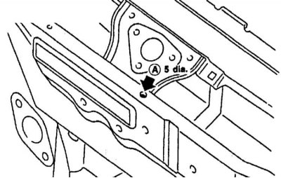
Upper central radiator support
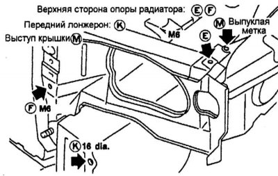
Upper side of radiator support, Front side member, Cover projection, Raised mark
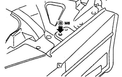
Outer side of the engine compartment opening
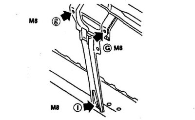
Center and bottom edge of the radiator
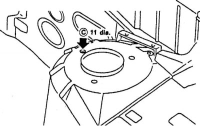
Suspension strut support and front side member (left side)
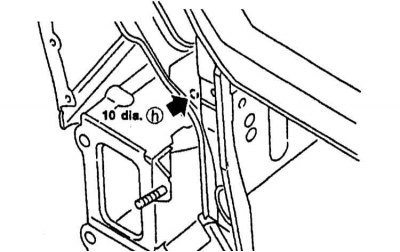
Front spar
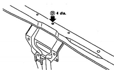
Upper central radiator support
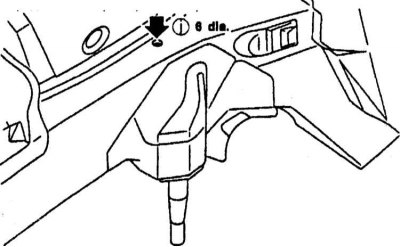
Right front side member
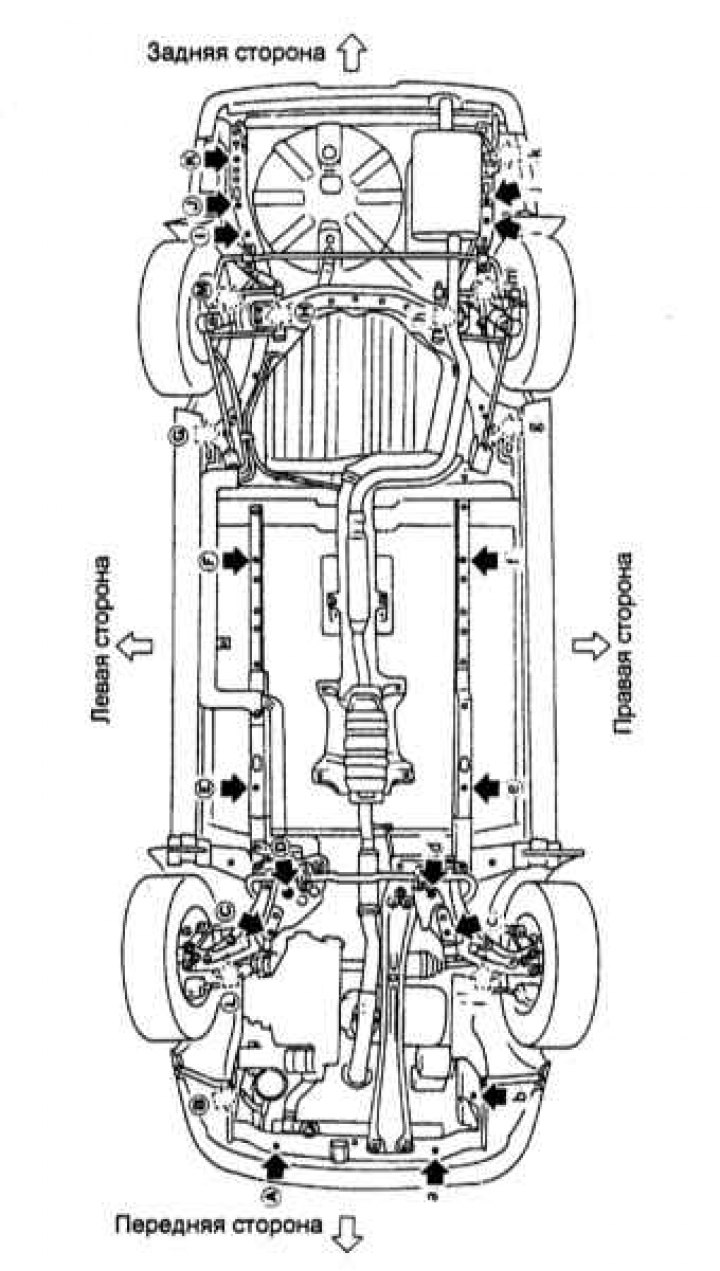
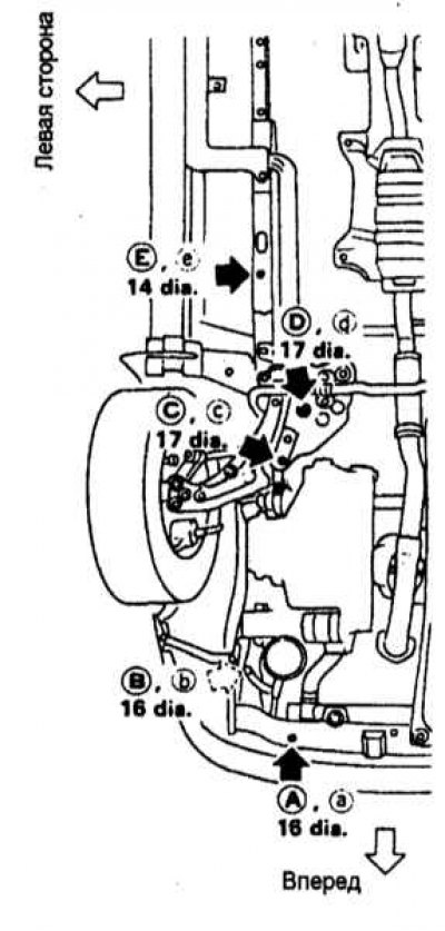
Geometry of body elements of the bottom of models produced since 1995.
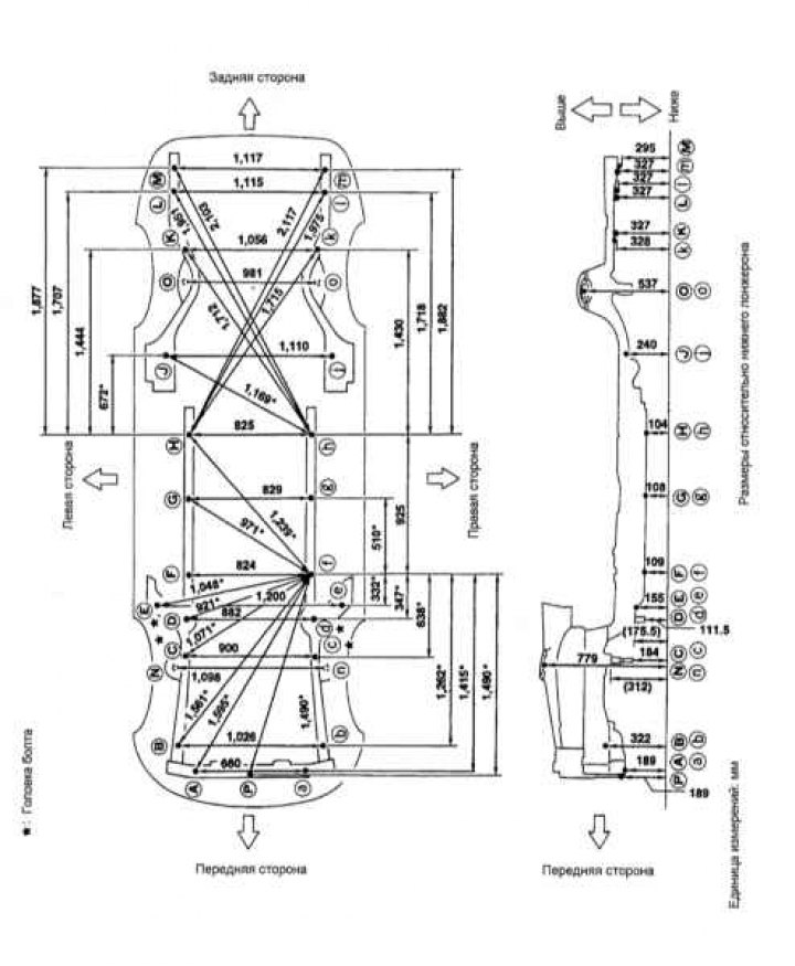
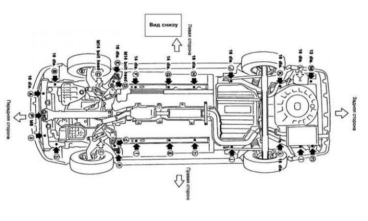
Coordinates:
A, a
X: 330
Y: -710
Z: 188.8
B, b
X: 513
Y: -540
Z: 322
C, c
X: 450
Y: 68
Z: 184
D, d
X: 441
Y: 354
Z: 111.5
E, e
X: 600
Y: 430
Z: 154.9
F, f
X: 412
Y: 700
Z: 109
G, g
X: 414.5
Y: 1.210
Z: 108.4
H, h
X: 412
Y: 1.625
Z: 104
J, j
Suspension rod installation hole
X: 555
Y: 2.185
Z: 239.5
TO
X: 512
Y: 3.000
Z: 326.6
k
X: -544
Y: 2.982
Z: 328.2
L
X: 540
Y: 3.272
Z: 326.6
l
X: -575
Y: 3.280
Z: 326.6
M
X: 546
Y: 3.454
Z: 295.4
m
X: -570.5
Y: 3.450
Z: 326.
Front and rear upper strut mount centers
Coordinates:
N, n
X: 548.8
Y: 28.7
Z: 779.3
Oh, oh
X: 490.3
Y: 2.621
Z: 537.2
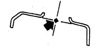
Front: N, n 87 diam.
Rear: Oh, o 61.4 dia
Suspension rod installation hole
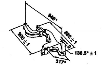
Front suspension element