


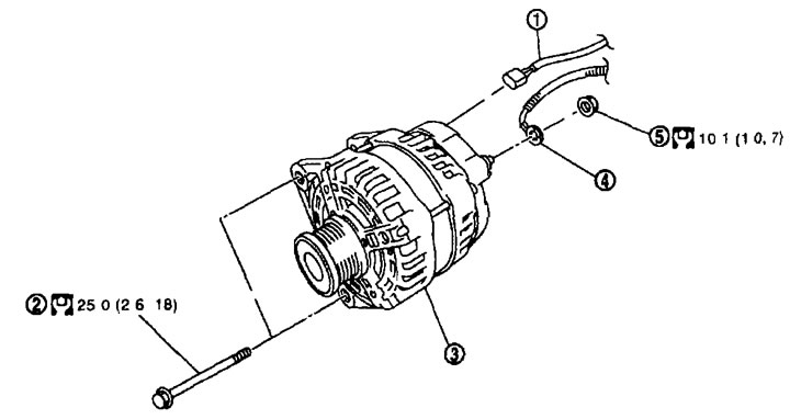
Removal. 1. Generator connector; 2. Generator mounting bolt; 3. Generator; 4. Wiring of terminal "B"; 5. Terminal "B" nut.
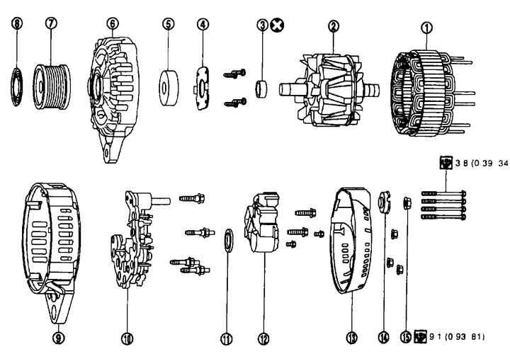
Disassembly. Type: LR1140-802C. 1. Stator assembly; 2. Rotor assembly; 3. Rotor spacer; 4. Clip; 5. Front bearing; 6. Front bracket assembly; 7. Pulley; 8. Pulley cap; 9. Rear bracket assembly; 10. Diode assembly; 11. Double labyrinth seal; 12. Voltage regulator assembly; 13. Back cover; 14. Bushing; 15. Nut of terminal "B".
Removal and installation
Removal
1. Disconnect the cable from the negative battery terminal.
2. Remove the engine cover. See chapter "Mechanical part of the engine".
3. Remove the drive belt. See chapter "Mechanical part of the engine".
4. Disconnect the connector (A) from the generator.
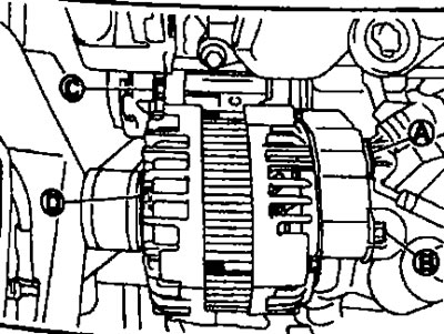
5. Unscrew the nut of terminal "B" (A) and disconnect the wiring of terminal "B".
6. Unscrew the upper mounting bolt (C) of the generator.
7. Completely loosen the lower generator mounting bolt (D) and remove it until the bolt head contacts the side member, then remove the generator from the vehicle forward.
Note: The alternator can be removed with the bolts by pulling it forward and using the slot for the alternator bracket bolt.
8. Remove the generator from the vehicle in an upward direction.
Installation
Installation is performed in the reverse order of removal.
Attention:
- Tighten the terminal "B" nut with care.
- Tighten the generator bolts by hand in order from bottom to top, then tighten them in order from top to bottom.
- Generator surface from the front side (from the pulley side) is the control. Fix the front side to the generator, then tighten the bolts.
- Install the generator and check the belt tension. See chapter "Mechanical part of the engine".
Disassembly and assembly
Disassembly
Rear bracket assembly
1. Remove the back cover.
2. Remove the voltage regulator assembly.
3. Separate the front bracket assembly, stator assembly and rear bracket assembly.
Note: Heat the center of the rear bracket assembly to approximately 30-50°C.
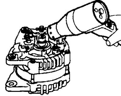
- Insert the tip of a suitable tool into the gap between the front cover and the stator core and separate the front side (front bracket assembly, rotor assembly) and the back side (rear bracket assembly, stator assembly, diode assembly).
Caution: Do not damage the stator assembly.
Front cover
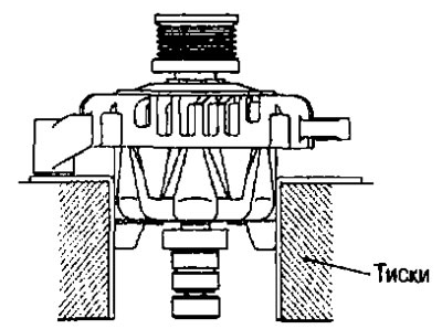
1. Secure the rotor in a vice.
The full article is available on the resource (NISSANBOOK.ru)
Attention:
- Do not damage the rotor.
- When securing the rotor in a vice, place copper strips or a thick cloth underneath.
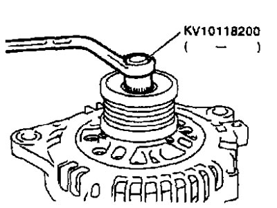
2. Using a suitable tool, remove the cap from the pulley.
3. Using the generator pulley adapter (special tool) remove the generator pulley.
Assembly
Rear bearing
Attention:
- Once the rear bearing is removed, do not reuse it. Replace it with a new one.
- Do not lubricate the outer race of the rear bearing.
Installing the back cover
1. Install the brush assembly, diode assembly, regulator assembly and stator assembly.
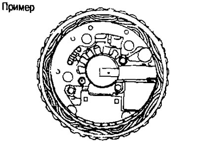
2. Lift the brushes with your fingers and install them on the rotor.
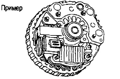
Note: Do not damage the sliding surface of the slip rings.
Examination
Checking after disassembly
Checking the rotor
1. Checking the resistance.
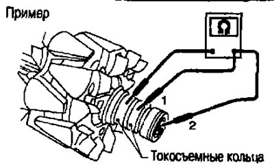
Resistance: See below. "Technical data and specifications".
- If the resistance is different from the norm, replace the rotor.
2. Insulation testing.
- If there is continuity, replace the rotor.
3. Check that the slip rings are not worn.
- Minimum outside diameter of slip ring: See below. "Technical data and specifications".
- If the measured value differs from the norm, replace the rotor.
Checking the brushes
1. Check if the brushes rotate freely.
- If they are sticking, check the brush holder and clean it.
2. Check if the brushes are worn out.
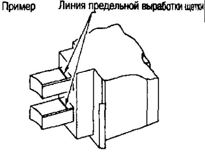
- If the wear has reached the limit line, replace the brush.
Stator check
1. Conductivity test.
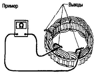
- If there is no conductivity, replace the stator
2. Checking the conductivity to ground.
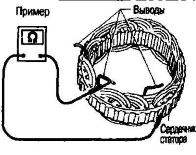
- If there is conductivity, replace the stator.