


Table of contents: Checking the traction relay - all…↓ Hitachi S114-390A and 391A ↓ Mitsubishi M3T33981, M3T33981H and…↓ Hitachi S114-392 and 393 ↓ Mitsubishi M2T53781 and M2T53785 ↓ Lucas/Magneti Marelli M78R ↓
1. Remove the starter as described above.
2. Clean the block from dirt.
Checking the traction relay - all types
3. Before checking the traction relay, disconnect the battery and engine wires from the traction relay terminals and disconnect the switch wire from the flat terminal.
4. Using a multimeter (in resistance measurement mode) or battery and lamp, check the traction relay as follows.
5. Ring the connections between the flat clamp "S" of the traction relay and the relay body, between the clamps "S" and "M". If there is no resistance, the windings are defective, and the traction relay must be replaced.
6. To check the operation of the traction relay, connect a battery (12 V) and an 18-21 W lamp between the traction relay motor and the battery pole; there should be no short circuit. Connect the wiring between the positive battery terminal and the flat terminal of the relay. The traction relay should operate and the lamp should light; if not, the relay contacts are bad and it should be replaced.
7. To replace the relay, disconnect the wires, unscrew the screws, remove it, disconnect the relay or plunger from the drive lever.
8. When installing, lubricate all contact points between the relay plunger and the drive lever. Install the relay by connecting the plunger to the drive lever and the spring, tighten the screws.
Hitachi S114-390A and 391A
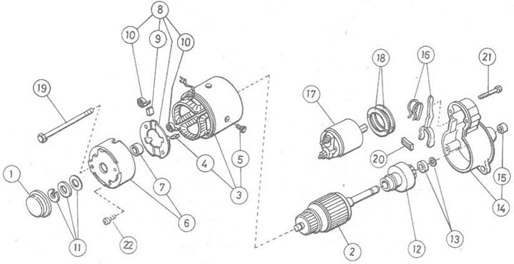
Figure 12.4. Starter - Hitachi S114-390A and 391A: 1. Dust cap; 2. Anchor; 3. Yoke and excitation winding assembly; 4. Positive brush; 5. Screw; 6. Back cover elements; 7. Bushing; 8. Brush holder elements; 9. Negative brush; 10. Brush spring; 11. Thrust washer and C-clamp; 12. Assembly of the drive gear; 13. Bearing and retaining ring; 14. Front cover elements; 15. Bushing; 16. Drive lever and spring; 17. Traction relay; 18. Adjusting plates; 19. Tie bolt; 20. Dust cap; 21. Screw; 22. Screw
9. Remove the traction relay as described above.
10. Remove the dust cap from the back cover.
11. Remove the C-clamp and thrust washers.
12. Unscrew the tie bolts and screws securing the brush holder to the back cover, remove the back cover.
13. Remove the springs, release the two positive brushes and remove the brush holder from the armature.
14. Remove the yoke, anchor and drive lever.
15. If the starter motor is removed, lower the pinion stop bearing down the shaft, remove the retaining ring, stop bearing, disconnect the motor assembly from the armature shaft.
16. Check all components, replace if necessary.
17. The anchor can be checked with an ohmmeter, connecting the probes to adjacent contacts around the switch (Figure 12.5). If there is a break between any pair, the anchor must be replaced.
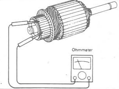
Figure 12.5. Checking the armature windings
18. Now check for a short circuit between each switch contact and the armature shaft. If there is a short circuit, the armature must be replaced.
[The original can be read on the website: nissanbook.ru]
19. Check the brushes for wear. If they are worn to the specified minimum length or less, they must be replaced.
20. The excitation windings can be checked with an ohmmeter, between the (+) terminal of the excitation winding and the positive brush (Figure 12.6). If there is a break, replace the excitation winding.
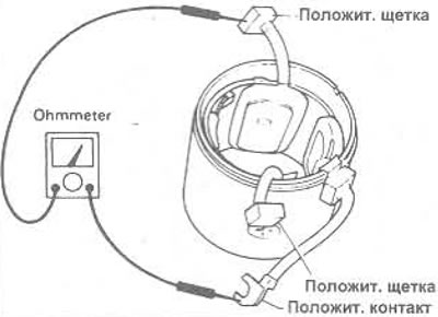
Figure 12.6 Checking the excitation windings
21. Now check for a short circuit between the positive terminal of the excitation winding and the yoke. If a short circuit exists, then the excitation windings must be replaced.
22. Check the correct operation of the drive pinion clutch. It should jam when rotating against the engine rotation and rotate freely in the opposite direction.
23. Assembly is carried out in reverse order.
24. The clearance between the pinion and the stop bearing must be certain. To adjust, use plates of different thickness installed between the relay and the front cover. Connect the wiring to the "M" clamp.
Mitsubishi M3T33981, M3T33981H and M3T30581
25. These blocks are very similar to the Hitachi engines described above, the only significant difference being that the thrust washers and C-clamp are not installed.
26. According to Figure 12.7 and the information given in the Specifications, proceed as described in the points above.
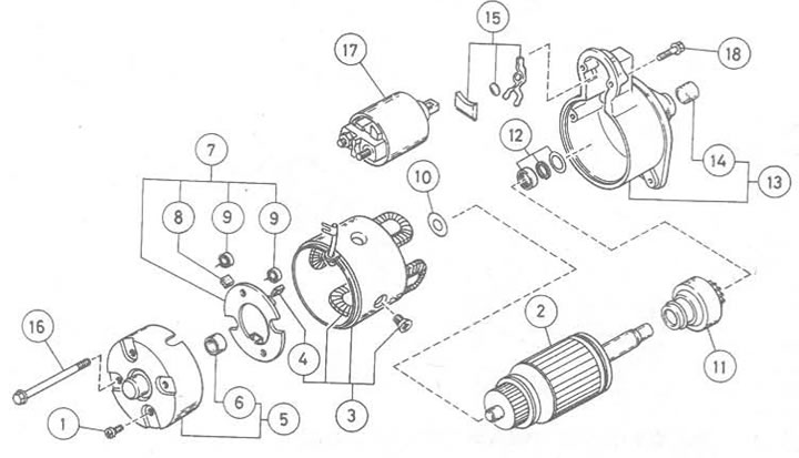
Figure 12.7. Starter - Mitsubishi M3T33981, M3T33981H and MZTZ0581: 1. Screw; 2. Anchor; 3. Yoke and excitation winding assembly; 4. Positive brush; 5. Elements of the back cover; 6. Bushing; 7. Brush holder elements; 8. Negative brush; 9. Brush spring; 10. Thrust washer elements; 11. Drive gear; 12. Bearing, bracket and thrust washer; 13. Front cover elements; 14. Bushing; 15. Elements of the drive lever; 16. Tie bolt; 17. Traction relay; 18. Screw
Hitachi S114-392 and 393
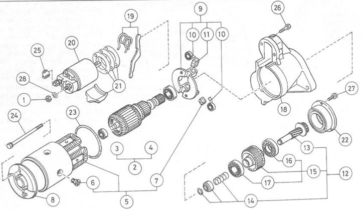
Figure 12.8. Starter - Hitachi S114-392 and 393: 1. Clamp nut; 2. Anchor and bearings; 3. Rear bearing; 4. Front bearing; 5. Yoke and excitation winding assembly; 6. Screw; 7. Positive brush; 8. Back cover; 9. Brush holder elements; 10. Brush spring; 11. Negative brush; 12. Gear and clutch assembly; 13. Pinion shaft; 14. Bearing, bracket and spring; 15. Assembling the coupling; 16. Front bearing; 17. Rear bearing; 18. Front cover; 19. Drive lever and spring; 20. Traction relay; 21. Adjustment plates and dust cap; 22. Bearing retainer; 23. O-ring seal; 24. Tie bolt; 25. Clamp cover; 26. Screw; 27. Screw; 28. Gasket
27. Mark the alignment of the yoke, front and rear covers relative to each other.
28. Unscrew the tightening bolts and remove the back cover.
29. Disconnect the yoke, armature and brush holder from the front cover.
30. Disconnect the two positive brushes, remove the brush holder.
31. Remove the anchor from the yoke.
32. Remove the drive lever and dust caps.
33. Unscrew the bearing retainer, remove the clutch assembly and shaft from the front cover. Disassemble the assembly if required as described above.
34. Check all components as described above.
35. Assembly is carried out in reverse order.
36. Check the clearance between the drive pinion and the bearing. Measure the height from the front end of the pinion to the front cover of the starter, pull the pinion manually until it contacts the bearing, measure the height again. If the difference is outside the specified tolerance, adjust the installation by selecting adjusting plates.
Mitsubishi M2T53781 and M2T53785
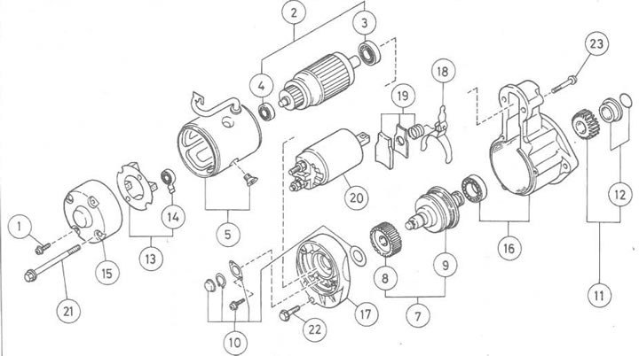
Figure 12.9. Starter-Mitsubishi M2T53781 and M2T53785: 1. Screw; 2. Anchor and bearings; 3. Front bearing; 4. Rear bearing; 5. Yoke and excitation winding assembly; 6. Elements of the drive gear; 7. Assembly of gear and shaft; 8. Reduction gear; 9. Pinion shaft and coupling; 10. Thrust washer, gasket and cover; 11. Gear elements; 12. Bearing and bracket; 13. Brush holder elements; 14. Brush spring; 15. Back cover; 16. Front cover and bearing; 17. Central suspension; 18. Drive lever; 19. Spring elements; 20. Traction relay; 21. Tie bolt; 22. Screw; 23. Screw
37. Remove the relay.
38. Mark the position of the front cover, center suspension, yoke and rear cover relative to each other.
39. Unscrew the tie bolts and screws securing the brush holder to the rear cover, remove the rear cover.
40. Remove the positive brushes from the brush holder by pressing the spring back, then remove the brush holder. If any of the brushes are worn to the specified minimum length, the brush holder assembly must be replaced.
41. Disconnect the yoke and armature from the front cover and center suspension assembly.
42. Replace the armature bearings if necessary.
43. Check the excitation windings if necessary.
44. Remove the rear cover of the pinion shaft.
45. Remove the screw and separate the center suspension from the front cover.
46. Remove the bracket from the front crankshaft gear, remove the bearing, gear and (where is available) spring.
47. Disconnect the drive lever, reduction gear and gear shaft assembly from the front cover.
48. Check all components as described above.
49. Assembly is carried out in reverse order.
50. When installing the reduction gear and gear shaft assembly, install the thrust washers, center hanger, gasket. Press the gear shaft as far as possible, measure the axial pressure gap. If the gap is greater than a certain value, adjust it with thrust washers.
Lucas/Magneti Marelli M78R
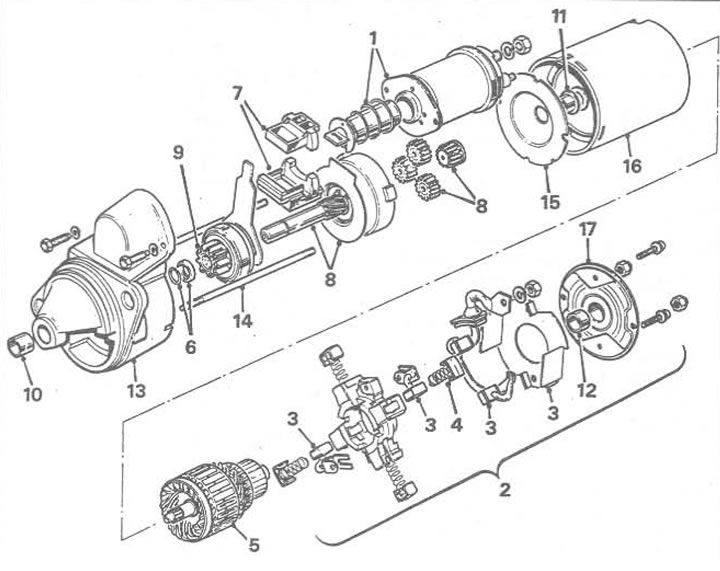
Figure 12.10. Starter - Lucas/Magneti Marelli M78R: 1. Relay and plunger; 2. Commutator suspension and brush holder assembly; 3. Brush; 4. Brush spring; 5. Anchor; 6. Thrust ring; 7. Starter lever and sealing ring; 8. Pinion shaft and reduction mechanism; 9. Assembling the drive gear; 10. Bushing; 11. Bushing; 12. Bushing; 13. Drive suspension; 14. Tie bolts; 15. Intermediate suspension; 16. Yoke and excitation winding assembly; 17. Commutator suspension
51. Remove the traction relay and plunger as described above.
52. Unscrew the two nuts and remove the commutator end hanger.
53. Remove the rubber sealing ring from the yoke, remove the brush holder assembly with brushes.
54. Disconnect the yoke from the drive suspension and anchor.
55. Remove the anchor from the step-down block. Then the anchor drive.
56. Remove the reduction unit including the lever and drive assembly from the drive side suspension.
57. Remove the ring from the shaft. Remove the pinion assembly and thrust ring.
58. Check the condition of the brushes and the tension of the springs.
59. Check the condition of the armature, excitation windings and pinion assembly as described above. The armature and pinion shaft bushings can be replaced separately (regardless).
60. Assembly is carried out in reverse order. Check the clearance of the gear jump ring.