Valve drive mechanism (injection engine)
1. Check levers for wear.
2. Measure the diameter of the hydraulic elements and replace if it lies outside the range of 16.690 - 16.994. Using an internal micrometer, measure the opening of the elements (17.000 - 17.020). The difference between the obtained dimensions gives the value of the backlash, which should lie in the range of 0.07 - 0.040 mm.
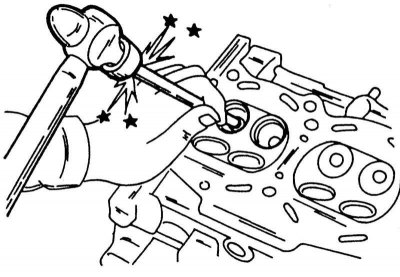
Knocking out the valve guide. Knock it out from the indicated side.
Valve seats
1. For all measurements mentioned, the corresponding size is indicated in Specifications. The dimensions for individual engine models differ, there is even a difference between both injection engines. Seats in the cylinder head should be machined to the required angle with a milling cutter or grinding stone. The exact chamfer angles of the valve seats are specified in Specifications at the beginning of the chapter. The width of the chamfer of the valve seat is different for carburetor and injection engines. Follow the correct size.
2. To reduce the bevel width of the seat, cutters with different angles are available, which are also given in Specifications at the beginning of the chapter.
Valves should be lapped in the usual way, a good but non-installable valve should be used for lapping.
3. If the chamfers of the valve seats are badly worn, new seats can be installed, while the cylinder head should be drilled to the appropriate size. This work must be carried out by a Nissan workshop, as the valve seats must always be installed concentrically with the valve guides.
Valves
1. Check valve stems for wear, gouging or cracks. Apply a steel ruler to a well-cleaned valve stem and check that the stem is straight. Bending is not allowed, as the valve will stick in the guide. Check the valve discs for carbon deposits or craters. There must be a certain distance between the upper surface of the valve and the upper edge of the chamfer of the valve. This dimension is referred to as the flap width and must be within certain limits. Never underestimate the minimum size. Valve discs can be ground with a special machine, provided that the required edge thickness is maintained.
2. If the ends of the valve stems are no longer smooth (they can no longer be correctly actuated by rocker arms or pushrods) they can be sanded, provided that they are not worn off more than 0.2 mm.
Valve guides
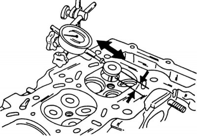
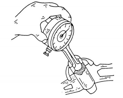
The valve guides are pressed into the cylinder head. If clearance between valve stem and valve guide is too large (more than 0.10 mm), guides can be replaced. Check the clearance first. To do this, insert the valve into the head as shown in the illustration below and remove it by 15 mm. Install the dial indicator as shown and move the valve from side to side. If the play is more than 0.2 mm, the guide must be replaced. In this case, new valves must be installed.
Check the valve stem for wear in the bore.
1. There are repair size guides for repairs (different diameters for injection engines) and the holes in the head should be reamed accordingly to fit the new rails.
2. Be sure to maintain the specified size to ensure an accurate fit. Before pressing in new guides, the holes must be reamed to the specified size.
3. Re-heat the cylinder head to 110 - 130°and drive new guides from the top into the head until the protruding part (size «L» in the illustration below) will not have a length of 14.0 -14.2 mm for an injection engine or 11.5 - 11.7 mm for a carbureted engine. This work should be done very slowly and carefully so as not to drive the guide too deep. After all the guides are clogged, cool the head and ream the guide holes with an appropriate size reamer. Work with special oil, always on the side of the combustion chamber.
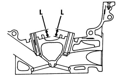
Size "L" - the size of the protrusion of the guides.
4. Accurate valve stem play can be calculated by measuring the outer diameter of the stem and the inner diameter of the guide.
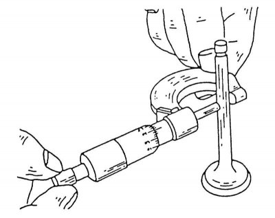
Measuring the diameter of valve stems. Measure in three places along the entire length.
5. Hole measurement requires an internal micrometer as shown in the illustration below. To get the backlash value, you need to subtract one dimension from the other.
Measuring the opening of the valve guide with a dial indicator.
6. After reboring the guides, always chamfer the valve seats to keep the guides and seats aligned. Otherwise, the valves will not close tightly.
Valve springs
It is recommended to always replace the valve springs if the engine has high mileage. The spring can be checked by putting the old and new springs abutting each other on the bolt and tightening the nut with the appropriate washer. Tighten the nut until the springs are compressed and measure the length of the springs. If the old spring is 10% shorter than the new one, the entire set must be replaced. To accurately check the springs, a special testing device is required. If such a device is available, the installation load and the associated spring length can be checked. Place the springs one by one on a flat surface (glass) so that the closed loop is at the bottom. Install a steel square to the spring (see illustration below). Measure the gap between the square and the top, which should not exceed the specified value. Otherwise, the spring is bent and must be replaced.
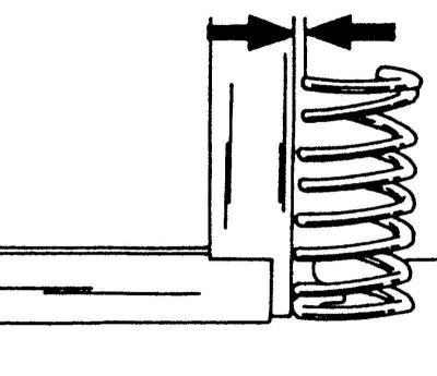
Check valve spring for bending. Install the spring as shown and check the top side deflection.
Valve springs should be installed with the closed end down. If you look at the spring, you can see that on one side the coils are farther apart than on the other side.