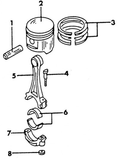
Piston parts
1 - piston pin; 2 - piston; 3 - piston rings; 4 - connecting rod bolt; 5 - connecting rod; 6 - connecting rod bearing shells; 7 - connecting rod bearing cover; 8 - connecting rod bearing nut
Piston parts are shown in the illustration above. To remove the pistons, the engine must be dismantled and the cylinder head removed. The oil pan must also be removed to get to the connecting rod bearings. Check out the related sections.
Pistons and connecting rods are pushed out with a hammer handle from the inside of the cylinder block after the covers and connecting rod bearing shells are removed. Before carrying out this work, please read the following notes regarding the designation and direction of installation:
Each piston and corresponding connecting rod should be identified by the number of the cylinder from which they are removed. This is best done by writing the cylinder number on the piston crown. Also mark the piston with an arrow pointing to the front of the engine. When the piston is later cleaned of oil deposits, the arrow should be reapplied.
When removing the piston with connecting rod, observe the exact installation position of the connecting rod bearing cap, and immediately after removal, check the connecting rod and bearing cap for the presence of the cylinder number on one side.
The bottoms of the pistons have a notch on the edge (injection engine) or arrow (carbureted engine), which should face forward. The connecting rods have oil spray holes. With parts installed, oil holes, connecting rod bearing designations and direction «forward» should be in the position shown in the illustration below. The illustration shows the details of the injection engine. On a carbureted engine, the reverse is true, i.e. the number of the connecting rod and cap is on the same side as the oil spray hole.
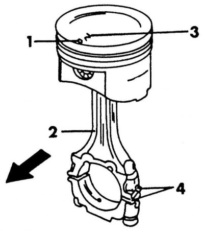
Correctly assembled piston and connecting rod of an injection engine. The carburetor engine has marks (4) and oil hole (2) should be on the same side
1 - before; 2 - oil spray hole; 3 - piston size; 4 - cylinder number
1. Mark the bearing shells with respect to the connecting rods and caps. Also color-code the top and bottom earbuds on the back.
2. Remove covers and bearing shells.
3. Push the pistons and connecting rods with a hammer handle from the inside of the cylinder block up. If it is necessary to remove the carbon ring on the top side of the cylinder bores with a scraper.
4. Remove the piston rings in order using pliers through the piston crown as shown in the illustration below. If the rings are to be used again, they should be marked. If special piston ring pliers are not available, metal strips can be inserted under the ring on opposite sides of the piston. Be sure to place one strip under the joint of the ring to avoid scratches.
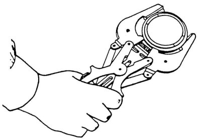
Removing or installing piston rings using special pliers.
5. Press the piston pin out of the piston and connecting rod. To do this, heat the piston to a temperature of 60 - 70° (hot water). Remove both circlips from the piston eye, position the piston properly and press the pin out of the piston and connecting rod eye. Assemble together all parts related to one piston and connecting rod.