


Table of contents: Checking the installation of the…↓ Measuring the play of connecting rod…↓
1. Carefully check all parts. If parts show signs of rust, scratches or wear, they should be replaced. Measure the vertical clearance of the piston rings in the piston grooves by inserting the rings one by one into the corresponding grooves, as shown in the illustration below. Using a flat feeler gauge, determine the clearance between the ring surface and the inner surface of the groove. If the ring clearance is more than 0.20 mm, or the rings or piston are worn, replace them as a set. The required clearance values are specified in Specifications.
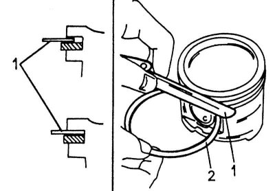
Measuring the vertical clearance of piston rings in the piston grooves. The feeler gauge should be inserted in accordance with the lower image in the left figure
1 - flat feeler gauge
2 - piston ring
2. Insert each piston ring one by one from the top of the crankcase into the cylinder. Using an upside-down piston, insert the rings to about the height of the piston. This will ensure that they sit evenly in the bore. Insert a flat feeler gauge into the gap between the ends of the ring, as shown on the right in the illustration below, to measure the gap in the lock. No one ring should have a gap greater than 1.0 mm. The required values are given in Specifications.
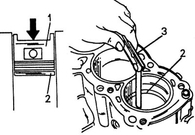
Checking the gap in the piston ring joints. Push the rings down with the piston upside down and then measure as shown in the right figure
1 - piston; 2 - piston ring; 3 - flat feeler gauge
3. If the gap is too small (for example, for new rings, which also need to be measured) the ends of the ring can be filed down. To do this, clamp a file in a vice and file the ends of the ring down. If the gap is too large, the ring must be replaced. If you only need to replace the piston rings without boring the cylinders, the gap in the locks must be measured on the underside of the cylinder. The upper and middle piston rings have the markings on the upper side (not on all engines). All rings should be installed so that the marking (if any) could be read from above. Check the piston pins and connecting rod bushings for rust and wear. If only one connecting rod is in poor condition, the entire set should be replaced.
4. The location of the piston pin in the piston should be such that the pin can be pushed into the piston by hand at room temperature (see illustration below). The clearance of the pin in the piston is 0.004 - 0.00 mm, but it is difficult to measure. Therefore, the check should be done by eye.
Checking the installation of the piston pin
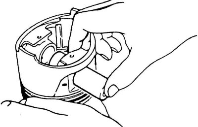
The piston pin should be pressed in with your thumb at room temperature.
5. Check the connecting rods for twisting and bending using a special device. If it is possible to use such a device, the limit values for twisting are 0.15 per 100 mm, 0.30 for bending.
Measuring the play of connecting rod bearings
This work is described in Section Crankshaft and crankshaft bearings in connection with the crankshaft. It is produced using a polymer hair "Plastigage" or you can measure the inner diameter of the connecting rod bearing and the outer diameter of the crankshaft journal.