2. Thoroughly clean valves, valve seat bevels, channels and sealing surfaces. Clean the inside of the valve guides by running a rag soaked in gasoline through them. This is all the more required if the valves have been lapped so that the remains of the grinding paste cannot get into the holes. When assembling, proceed as follows.
Injection engine
1. Install valve stem seals. The end of the valve with grooves for crackers should be wrapped in foil (from a pack of cigarettes). The oil seals are put on with a piece of pipe, after installing the valve spring cup. Do not damage the caps.
2. Insert the valves into the appropriate holes. The valves of the originally produced engines did not have designations. New valves in the middle may have the designation "53J" (intake valves) or "5J" (SR20DE engine exhaust valves) or "64Y" (SE20Di engine exhaust valves). Valves marked in this way can be installed instead of old ones.
3. Install the valve springs with closed coils towards the cylinder head. In addition, the lower part of the valve springs is color-coded. This side faces the cylinder head.
4. Put on the upper cup of the spring and compress the spring with a compressor or press so that it can be inserted into the grooves of the valve cotters. On illustrations shows how to install the valve spring compressor.
5. Release the constrictor and hit the valve spring with a hammer to make sure the nut is firmly seated.
6. If the cylinder head studs were replaced, they must be firmly screwed into the head, to do this, mutually lock the two nuts and install a wrench on the top nut.
7. Install the valve levers, wear washers, lever guides and hydraulic expansion joints according to illustrations. Now you should check the compensation elements. If the lever can be pushed 1 mm down, when the lever on the opposite side is pushed down, there is air in the respective element. The air must be removed as it will not come out on its own.
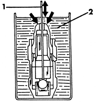
Checking the hydraulic compensation element. Push the piston down in the direction of the two arrows while the metal rod in the direction of the arrow presses the ball
1 - metal rod
2 - engine oil
8. Despite the fact that the work is associated with some difficulties, the air from the element should be removed, otherwise it will knock when the engine is running. To remove air, remove the element again, insert it into a vessel filled with impellent oil, so that the lower side rests against the bottom. Press the piston with your finger and insert a small rod into the valve hole. Move the rod up and down. In this case, the rod presses the check valve and displaces the air. The air is removed when the piston is no longer moving. The illustration above shows elements of this work. The rest of the cylinder head assembly is identical with its installation and has already been described previously.
Carbureted engine
To assemble the cylinder head of a carburetor engine, it is only necessary to install valves and removed parts. It should be remembered that it is necessary to adjust the valve clearance, as described in subsection valve guides. Valves are installed in accordance with the instructions above. Further assembly of the cylinder head is adequate to its installation and is described in Section Checking and adjusting valve clearances Chapters Ongoing care and maintenance.