Injection engines
Remove the valve levers, wear washers, lever guides and hydraulic expansion joints as illustrated below.
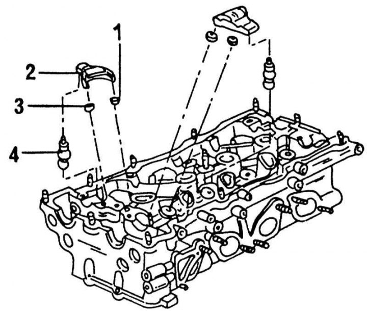
Details of the valve drive mechanism of the injection engine
1 - lever guide; 2 - valve lever; 3 - compensation washer; 4 - hydraulic compensator
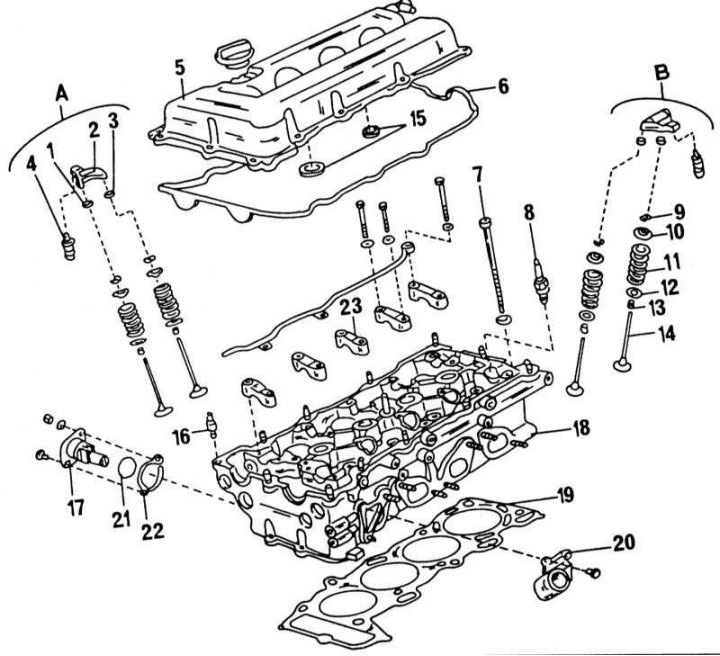
Elements of the cylinder head of the injection engine
A - inlet side
B - release side
1 - compensation washer; 2 - valve lever; 3 - lever guide; 4 - compensation element; 5 - cylinder head cover; 6 - cover gasket; 7 - cylinder head bolt; 8 - spark plug; 9 - valve crackers; 10 - valve spring cup; 11 - valve spring; 12 - valve spring cup; 13 - oil deflector cap; 14 - valve; 15 - round gaskets; 16 - bolt, 12-15 N·m; 17 - chain tensioner; 18 - cylinder head; 19 - cylinder head gasket; 20 - water outlet pipe; 21 - round seal; 22 - gasket; 23 - camshaft bearing caps
1. On the SR20Di engine, remove the EGR valve pipe.
2. Unscrew the heat shield from the exhaust manifold and loosen the manifold mounting. At the same time, weaken, starting from the outside to the inside.
3. On the SR20DE engine, unscrew the fuel lines.
4. Loosen the inlet pipeline starting from the outside towards the inside. On the SE20DE engine, unscrew the line from the inlet pipeline.
5. Unscrew the water outlet and the thermostat housing together with the water tube.
6. Remove valves. To do this, compress the valve springs with a compressor. The illustration shows a suitable compressor for this engine. Remove the valve cotters, spring cup and valve spring. If you don't have a compressor, place a piece of wood in the combustion chamber under the valve head and slide a piece of pipe over the top of the valve head. Hit the pipe with a hammer, and the valve cotters will pop out of the grooves and remain inside the pipe.
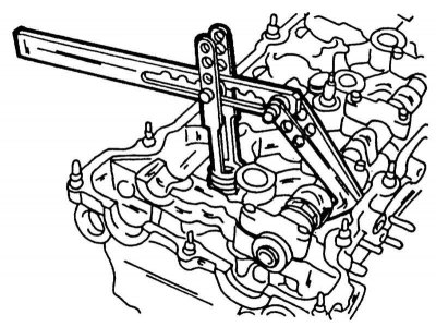
Removal of valves of the injection engine.
7. Remove the valve stem seals with pliers. Caps must always be replaced. On illustrations individual elements of the cylinder head are shown with the location of individual parts. The second camshaft rests on the same elements, however, one of the end caps is larger.
Carbureted engine
The cylinder head of a carburetor engine is already disassembled to some extent into separate elements during removal, that is, only valves remain in the cylinder head. They are removed in the same way as described above. Take out pushers and adjusting washers of pushers and connect according to valve number. The camshaft bearings of this engine are shown in the illustration below.
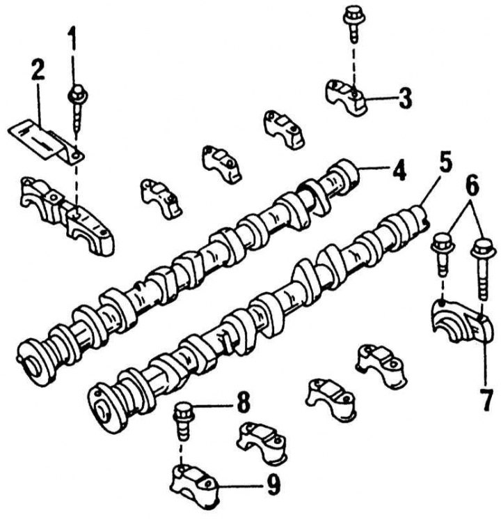
Camshafts and their bearings on a carburetor engine
1 - bolt, 9-12 Nm; 2 - chain guide; 3 - bearing cap; 4 - intake camshaft; 5 - exhaust camshaft; 6 - bolts, 9-12 Nm; 7 - distributor installation housing; 8 - bolts 9-12 Nm; 9 - bearing cover