Note. You will need the following special equipment to perform the procedures below: valve spring compression tool, micrometer, and flatness tester (edge of steel ruler).
Removing
Note. The cylinder head can, in principle, be removed as an assembly with the intake manifold and exhaust manifold, however, due to the significant weight and size characteristics of such an assembly, the compilers of this Guide recommend that the following procedure be followed.
1. Disconnect the negative cable from the battery.
2. Take care to protect the paintwork around the engine compartment from damage.
3. Empty the cooling system.
4. Remove the rocker arm assembly with push rods, intake manifold and exhaust manifold.
5. Loosen the hose clamps and disconnect the cooling and heating hoses that interfere with the removal of the cylinder head.
6. Give a bolt of fastening of an adjusting bracket of the generator on a head of cylinders.
Note. To avoid deformation of the cylinder head, do not loosen the cylinder head bolts until the engine has completely cooled down.
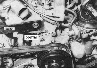
7. Give forward bolts of a head of cylinders in the neighborhood to the water pump (see accompanying illustration).
8. Gradually loosen the head mounting bolts in the reverse order shown in the accompanying illustration. When removing the bolts, be careful not to drop the washer from the #23 bolt into the engine.
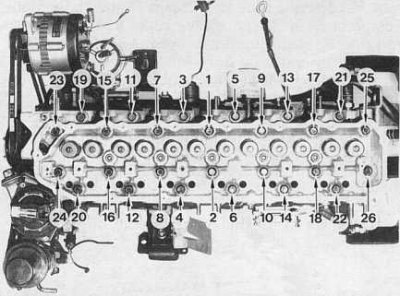
The order of tightening the cylinder head bolts is that the front bolts are not visible and must be tightened after the main bolts are tightened.
9. With the help of an assistant, remove the cylinder head from the engine compartment. Take care not to accidentally damage the mating surfaces.
Installation
Installation is in the reverse order.
1. Make sure that the mating surfaces of the block and cylinder head are absolutely clean - they should not have burrs, burrs and traces of the old gasket material.
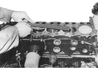
2. Check the cylinder head for deformation by measuring its flatness diagonally and along the mating surface (use a flatness meter (edge of steel ruler) and blade type probe - see accompanying illustration). If signs of deformation are detected, the head should be machined, bringing its condition in line with regulatory requirements (see tables of sizes and adjustments at the end of the guide), or replace.
3. Similarly check up flatness of an interfaced surface of the block of cylinders. Make necessary repairs (groove), or replace the block.
4. Lay a new head gasket on the engine block, making sure that its holes are correctly aligned with the guide pins and working holes in the block.
5. Install the cylinder head on the block, lightly lubricate the threads of the bolts and washers with oil and screw in the fasteners.
Note. Washers should be installed with chamfers to the heads of the bolts.
6. Loosely screw in the front head bolts.
7. Tighten the main mounting bolts in the order shown in the illustration according to the following scheme:
- Tighten the bolts in the first step (main) with a force of 29 Nm;
- Then tighten them with a force of 78 Nm;
- Completely loosen the bolts in reverse order;
- Re-tighten them to 29 Nm;
- Tighten the bolts with a force of 64÷74 Nm, or (which is preferable) using the protractor another 69°÷70°.
8. Tighten the front head bolts to 6.4÷7.5 Nm.
9. Reinstall the rocker arm and push rod assembly, as well as the intake manifold and exhaust manifold.
10. Start the engine and check for leaks.
Disassembly of the cylinder head
.Note. Overhaul of the cylinder head requires the use of special equipment. The purchase or rental of such equipment is usually not economically viable when repairing only one head. In view of the foregoing, it would be advisable to entrust the overhaul of the cylinder head to the specialists of the workshop of the dealership of the car manufacturer or service station. In some branded workshops, you can purchase a replacement remanufactured head on an exchange basis, which can significantly reduce vehicle downtime.
1. Remove the cylinder head from the engine.
2. Remove the thermostat cover from the cylinder head, remove the thermostat and remove traces of the old gasket material from the mating surfaces.
3. Remove carbon deposits from combustion chambers before removing valves. This will minimize the risk of damage to the valves and their seats.
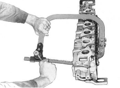
4. Lay the cylinder head on its side and, using a special tool, compress the springs of the first of the valves (see accompanying illustration).
5. Remove the crackers of the split lock from the valve spring plate (valve components are shown in the accompanying illustration).
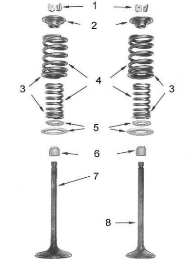
1 - crackers; 2 - plates of valve springs; 3 - turns with a shortened pitch; 4 - springs; 5 - saddles; 6 - oil seals; 7 - inlet valve; 8 - exhaust valve
6. Release the tool and remove the spring plate, springs and spring seats.
7. Using a needle file, remove visible burrs and roughness from the edges of the groove for installing split lock crackers on the valve stem, then remove the valve from the cylinder head body.
8. Acting according to the described scheme, remove all remaining valves, folding them in an orderly manner with reference to the installation sites.
Note. For orderly storage of valves, a rail with twelve numbered holes is perfect, into which the valves should be stuck with rods in the order they are installed in the head.
9. Carefully prying, remove the valve stem caps from the valve stems. Throw them away.
Cleaning and checking the condition of the head and its components
1. Thoroughly clean valves and discard defective (with burnouts, cracks and deformation of the rods).
2. Carefully remove accumulated deposits from head inlet and outlet ports, valve stems and valve guides. Be careful not to damage mating surfaces.
3. Clean the mating surface of the head, the water jacket passages, the support and the thermostat housing.
4. Wash the cylinder head in kerosene, rinse with water from a hose, then dry thoroughly to prevent corrosion.
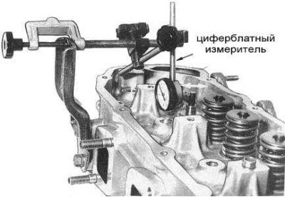
5. Insert each valve into its own guide bushing. Raise the valve so that the end of its stem protrudes 30 mm. Fix the dial gauge so that its plunger rests against the forming surface of the valve stem shank (see accompanying illustration).
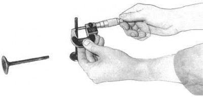
6. Rock the valve back and forth parallel to the plane of the rocker arm. If the meter detects a stroke greater than 0.2 mm, measure the inner diameter of the guide sleeve and the outer diameter of the valve stem with a micrometer (see accompanying illustration). Compare measurement results with regulatory requirements (see tables of sizes and adjustments at the end of the guide), replace worn components if necessary. Repeat procedures for all valves.
Note. Since in order to remove and install the guide bushings, the head must be heated to a temperature of 150°÷ 160°C, and the bushings themselves should be correctly deployed after installation, it is advisable to entrust this work to a specialist.
7. Replace all spherical plugs (water jacket squeeze plugs) cylinder heads, the serviceability of which is in doubt.
8. Check the flatness of the mating surfaces of the head and cylinder block (see subsection Removal and installation). If necessary, grind surfaces or replace non-repairable components.
9. Check up serviceability of functioning of the thermostat.
Restoration of working surfaces of plates and valve seats
Note. This work must be carried out by a qualified mechanic who has the special tools at his disposal. The compilers of this Guide recommend entrusting it to the specialists of a car service workshop.
1. Machine the plate of each of the valves at the angle specified by the standards (see tables of sizes and adjustments at the end of the guide). If necessary, grind the valve stem flat, but do not remove more than 0.2 mm of material. If the width of the cylindrical part of the generatrix of the surface of the plate (belt) out of range, the valve must be replaced.

1 - seat chamfer; 2 - valve disc belt; 3 - rod; 4 - groove for crackers of a split lock
2. Check the straightness of the valve stem. If excessive bending is found, also replace the valve.
3. When turning valve seats, be sure to equip the cutter with a special guide. As a result of processing, a smooth, inextricable working chamfer should be obtained.
4. Excessively worn seats must be replaced.
5. Once the seat has been machined, the seat bevel width must meet the regulations, which are different for inlet and outlet valves (see tables of sizes and adjustments at the end of the guide).
6. To check the development of the contact patch, lubricate the working surface of the valve disc with Prussian blue, then install the valve in the head and rotate, pressing it against the seat. After tearing off the valve disc, a uniform, unbreakable ring should form on the working chamfer of the seat, coaxial to the axis of the seat. Check the finish of all valves/seats in the same way.
Checking the condition of the valve springs
1. Measure the free length of the valve springs. Compare measurement results with regulatory requirements (see tables of sizes and adjustments at the end of the guide).
2. Check the springs for signs of deformation.
3. If a special diagnostic tool is not available, compare the length of the loaded spring with that of the new spring. To do this, rest the springs with their ends against each other, laying a flat plate or washer between them, then compress the assembly in a vice. After closing the vise jaws by approximately 13 mm, the length of a working spring should not differ from the length of a new one by more than 5%. Replace spring if necessary.
Cylinder head assembly
Assembly is carried out in the reverse order of dismantling.
1. Before assembling, make sure that the ports and valve seats are absolutely clean - there should not be any traces of foreign materials on their surfaces. Lightly oil the valve guides and install the spring seats.
2. Using a piece of suitable tube, fit the valve stem seals onto the guide bushings. The planting depth must be observed with maximum accuracy (see accompanying illustration).
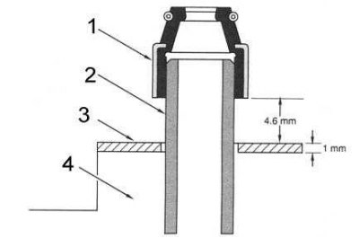
1 - oil cap; 2 - guide sleeve; 3 - spring seat; 4 - cylinder head
3. Lubricate the valve stems and insert them into their respective guide bushings.
4. Put the springs and their plate on the valve stem, making sure that the springs are turned in turns with a shortened pitch towards the head. Compress the assembly with a special tool.
5. Install split lock crackers into the groove on the shaft and release the tool. Lightly tap the end of the rod with a hammer to shrink the crackers in the groove.
6. Repeat the procedure for the remaining valves. Install the head to the cylinder block.