


Attention! To facilitate assembly, mark the brackets to be removed and mark the routing of wires and hoses.
Removal
1. Drain the coolant.
2. Remove the camshafts (see subsection 3.2.1.9).
3. Please note that the description below assumes removal of the head assembly with the exhaust and intake manifolds. This reduces the amount of work required to remove the head, but makes manipulation of the head more difficult due to the increased size and weight of the entire assembly. It is recommended to remove both manifolds first (see subsection 6.1.12 and subsection 6.1.13).
4. On engines with preliminary preparation of the fuel-air mixture (single-channel injection system) perform the following activities:
- remove the air filter;
- perform decompression of the fuel system and disconnect the fuel supply hose and return hose from the throttle chamber (plug all openings to prevent fuel loss and dirt from entering the fuel system);
- disconnect the throttle cable;
- disconnect the wiring connectors from the throttle body, intake manifold and other components;
- disconnect the brake booster, cooling system and crankcase ventilation system hoses from the corresponding valves and pipes mounted on the cylinder head;
- remove the intake manifold support bracket;
- disconnect the muffler inlet pipe from the exhaust manifold.
5. On engines with direct fuel injection (with multi-channel injection system) perform the following activities:
- remove the air filter and air duct;
- perform decompression of the fuel system and disconnect the fuel supply hose and return hose from the fuel distributor (plug all openings to prevent fuel loss and dirt from entering the fuel system);
- disconnect the throttle cable;
- disconnect the wiring connectors from the throttle body, intake manifold, and other components. Disconnect the wiring from the injectors and move it to the side so that it does not interfere with the removal of the cylinder head;
- disconnect the brake booster, cooling system and crankcase ventilation system hoses from the corresponding valves and pipes mounted on the cylinder head;
- remove the intake manifold support bracket;
- disconnect the muffler inlet pipe from the exhaust manifold.
6. On vehicles equipped with an automatic transmission, disconnect the downshift cable from the throttle body.
7. Loosen the clamps and disconnect the hoses from the coolant pump, heater core and oil cooler (if provided). Also disconnect the radiator hoses of the cooling system at the front of the cylinder head.
8. On Phase I direct injection engines, remove the starter (see subsection 7.6) then loosen and remove the bolt securing the coolant pipes to the rear of the cylinder block.
9. Disconnect the wiring connectors from the ignition distributor, from the ignition coil and from the transistor power supply. Disconnect the wiring sleeve from the clamps, move it away from the cylinder head. Unscrew the bolts and remove all ground wires secured to the cylinder head and to the intake manifold.
10. Loosen the bolts securing the generator bracket to the cylinder head.
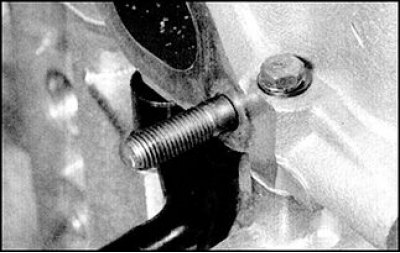
11. Loosen and remove the M6 bolts securing the cylinder head to the timing chain cover (if these bolts are not yet unscrewed), also unscrew the bolt at the front of the cylinder head.
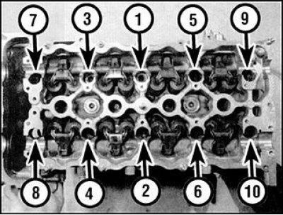
12. Working in the reverse order to that shown in the diagram, loosen all ten main cylinder head bolts. Loosen the bolts in several steps, 1/2 turn at a time, until the bolts can be loosened by hand.
13. Remove the bolts and washers, paying attention to their position in the cylinder head.
14. Remove the cylinder head. It is advisable to perform this operation with an assistant, since the head assembly with camshafts is quite heavy (especially if the collectors are not removed). Remove the gasket from the cylinder block, paying attention to the two installation pins. If the pins come out of the holes, remove them, remembering the initial installation position, and store them with the cylinder head. Also pay attention to the correct installation of the oil injectors in the cylinder block. If the injectors are loose and can be removed, remove them and store them with the cylinder head.
15. Check for damage on the separating surfaces of the cylinder head and block (deep scratches, chips, etc.). Minor damage can be removed with a file, but serious damage can only be removed by sanding.
16. If the head is to be disassembled for major repairs, then follow the description in the relevant subsection.
Preparing for assembly
1. The manufacturer recommends measuring the cylinder head bolts to determine their continued suitability. Measure the length of each bolt (having previously removed the washers) from the inner surface of the bolt head to the end of the threaded part. If the length of all the bolts is less than 158.2 mm, then the bolts can be used. If the length of at least one of the bolts exceeds 158.2 mm, then all the bolts in the set should be replaced. Considering the forces that the cylinder head bolts experience, it is strongly recommended to replace them regardless of their condition.
2. Before installing the cylinder head on the engine, thoroughly clean the separating surfaces of the head and block. Remove any remaining carbon deposits and gasket material with a hard plastic or wooden spatula, and also clean the piston bottoms from carbon deposits. Be especially careful when cleaning, as the surfaces can be easily damaged. Also take measures to prevent the carbon deposits being removed from entering the oil channels or cooling system channels in the cylinder block, otherwise the channels may become blocked and the lubrication of engine parts may be disrupted. Cover the openings of the oil channels, cooling system channels, and bolt holes in the cylinder block with duct tape and paper. To prevent dirt from getting into the gap between the piston and cylinder, coat the gap with consistent grease along the edge of the piston bottom. After cleaning the pistons, remove the grease from the gap with a brush and wipe off the remaining grease with a clean rag.
3. Check for damage on the separating surfaces of the cylinder head and block (deep scratches, chips, etc.). Minor damage can be removed with a file, but serious damage can only be removed by sanding.
4. If there is a suspicion of deformation of the separable surfaces, then check the deviation of these surfaces from the plane using a gauge.
Installation
1. Wipe dry the separating surfaces of the cylinder head and block. Replace the two dowel pins (if they were filmed) and insert the oil jets into the cylinder block.
2. Place a new gasket on the cylinder block, aligning the holes in the gasket with the pins.
3. With the help of an assistant, carefully install the head onto the cylinder block, aligning the head with the dowel pins.
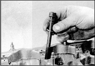
4. Lubricate the threads and the bottom of the bolt heads with clean oil. Place washers on the bolts and carefully insert the bolts into the corresponding holes in the cylinder head (dropping bolts into holes is not allowed). Install the bolts and tighten by hand.
 |
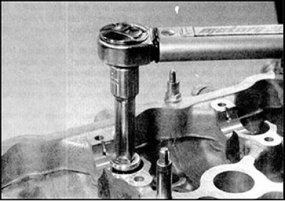 |
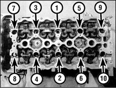
5. Tighten the 10 main cylinder head bolts in the sequence shown, to the torque corresponding to stage 1. Tighten with a torque wrench with a socket head.
6. After completing Stage 1 tightening, tighten the bolts to Stage 2 torque.
7. Wait a minute and loosen the bolts in the reverse order of the bolt tightening diagram in step 5. Loosen the tightening gradually, 1/2 turn at a time, until the bolts can be loosened by hand.
8. Again tighten the 10 bolts finger tight, then tighten in sequence to Stage 3 torque.
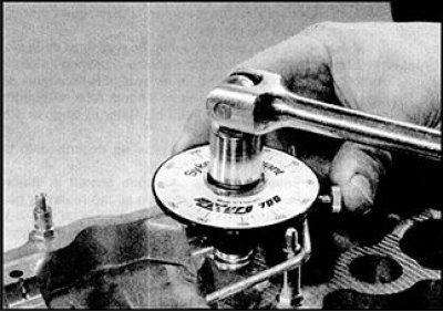
9. After completing stage 3, tighten the bolts to the angle specified for stage 4. It is recommended that you tighten the bolts at this stage using a spanner with an angle scale to ensure that the tightening requirements are met accurately. If you do not have a spanner with an angle scale, use paint to mark the bolt head and the cylinder head surface. The marks should be at the specified angle. These marks should be used as a guide when performing stage 4.
10. After completing Stage 4 of tightening the main cylinder head bolts, tighten the bolts to Stage 5 torque in the sequence shown.
11. After final tightening of the main cylinder head bolts, install the M6 bolts at the front of the cylinder head and tighten them to the specified torque.
12. Route the wiring as before, connect the wiring connectors to the ignition distributor, to the ignition coil and to the transistor power supply. Secure the wiring in place with straps and clamps.
13. Connect the ground wires to the cylinder head and manifold and tighten the bolts securely.
14. On Phase I direct injection engines, screw the coolant pipe mounting bolt into the cylinder block and tighten securely. Install the starter (see subsection 7.6).
15. Connect the cooling system hoses in the same order as they were installed originally, and secure the hoses with clamps.
16. Guided by the relevant Part in Chapter 4, perform the following operations:
- connect all wiring, hoses and control cables to the fuel system components and to the intake manifold;
- install the intake manifold support bracket;
- attach the exhaust pipe to the exhaust manifold;
- install the air filter and air duct (if provided).
17. On vehicles equipped with an automatic transmission, connect and adjust the downshift cable.
18. Install the camshafts (see subsection 3.2.1.9).