


Removal air from the hydraulic regulator
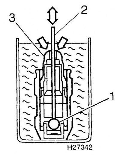
1. Ball valve
2. Rod
3. Plunger
Removal
1. Remove the camshafts (see subsection 3.2.1.9).
2. Prepare 16 clean plastic bags and number them from 1 to 16. You can also use a box with 16 compartments.
 |
 |
[See the source on the portal NissanBook.ru]
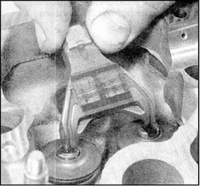
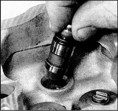
3. Remove the first valve drive lever, remove the hydraulic regulator from the hole in the cylinder head and place it in a bag together with the lever, observing the working position of these parts.
Attention! The hydraulic regulator must be stored only in the working position. When stored horizontally or upside down, air will get inside the regulator, which must be removed before assembly following the recommendations set out in paragraphs 9 and 10 (see below).
4. Remove the spacers and guide discs from the ends of the valves and place these parts in a bag along with the hydraulic regulator.
5. Repeat the steps in paragraph 3 and remove the valve drive levers, hydraulic regulators, spacers and guide discs of the remaining valves. Do not mix up the levers and hydraulic regulators, otherwise these parts will be subject to increased wear.
Checking the status
1. Check the contact surface of the lever with the camshaft cam for signs of wear and damage. If the levers are worn, the camshaft cams will also show increased wear (see Fig. subsection 3.2.1.9). Replace the levers if necessary.
2. Check for signs of increased wear on the hydraulic regulators and in the mating holes in the cylinder head. If you have the necessary measuring tool, the degree of wear can be determined using direct measurements. To do this, measure the inner diameter of the hole for the hydraulic regulator in the cylinder head and the outer diameter of the hydraulic regulator. The gap in the hydraulic regulator is equal to the difference between these diameters. Compare the resulting gap value with the standard one specified in the section (see subsection 3.2.1.1). Replace worn parts if necessary.
3. Check for signs of wear on the lever guide discs and replace if necessary.
Installation
1. Before assembly, it is necessary to check the thickness of each spacer shim to determine its suitability for further use. This operation is especially necessary if new valves and valve seats are to be installed, or if the valves have been reground. The procedure for checking the shim thickness is described in paragraphs 2–5. If the cylinder head has not been repaired and measuring the shim thickness is impractical, then continue assembly, following the instructions in. p. 8 and so on.
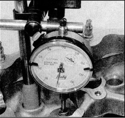
2. Install the actuator lever guide disc onto the end of the valve from which the disc was removed (this is very important, see. p.13). Attach the pointer indicator to the cylinder head, bring the movable probe of the indicator leg into contact with the thrust surface of the guide disk, which is in contact with the valve drive lever. Set the indicator scale to zero.
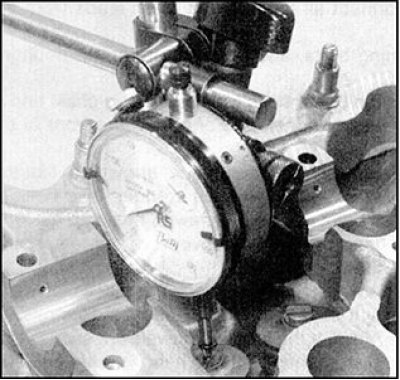
3. Then carefully lift the indicator leg probe and turn the indicator strictly parallel to the initial position. Bring the indicator probe into contact with the end of the other valve, which will be acted upon by the drive lever, i.e. the second valve from the same cylinder.
Attention! When turning, the indicator must move strictly parallel to the initial position, otherwise the readings will be erroneous.
4. Read the indicator reading, which will be equal to the distance between the end of the valve stem and the thrust surface of the guide disk, which is affected by the valve drive lever, and record this reading. To ensure that the indicator head moves strictly parallel during the measurement, turn the head back to the original position, in which the indicator probe touches the thrust surface of the guide disk. The indicator reading when returning to the original position should be zero. Repeat the above measurements for each pair of intake and exhaust valves of all cylinders. Record the measurement results.
5. Based on the measurements taken, determine the appropriate thickness of the spacers for each pair of valves. The thickness of the spacer must be exactly equal to the measurement result, but the manufacturer has set a tolerance of ±0.025 mm.
Attention! Spare parts are supplied with gaskets with thickness from 2.800 to 3.200 mm with a step of 0.025 mm.
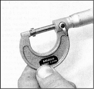
6. The thickness value is marked on the bottom surface of the gasket (for example, 2875 means a thickness of 2.875 mm), However, it is highly advisable to measure the actual thickness of the gasket being replaced with a micrometer, as it is possible that the thickness may have decreased due to wear.
7. Place the spacers on the appropriate valve, ensuring that the marked surface faces downwards.
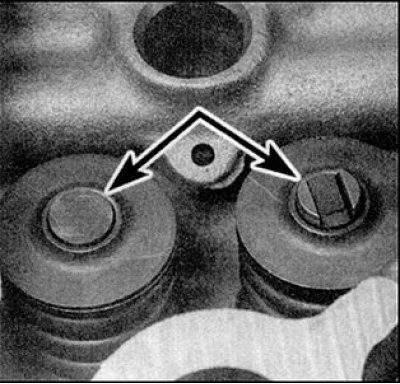
8. If the shim thickness was not measured, install the guide discs and adjusting spacers (indicated by arrows) onto the corresponding valves, ensuring that the surface of the gaskets with the markings faces downwards.
9. Before installing the hydraulic regulators, make sure there is no air inside them. To do this, press the plunger of the regulator (the regulator must be in a vertical position, with the plunger facing upwards), the plunger movement should not be felt. If the plunger moves more than 1.0 mm, then there is air inside the hydraulic regulator. If air is detected inside the regulator, or if a new regulator is installed, then the air should be removed by doing the following.
Attention! When the engine is running, air from the hydraulic regulators is not removed spontaneously. If the regulators are installed without removing the air that has gotten inside, their normal operation will be disrupted and increased noise will be heard.
10. Prepare a small vessel, the dimensions of which are slightly larger than the dimensions of the hydraulic regulator, and a rod (for example, a piece of welding electrode), which passes into the hole in the plunger of the regulator. Fill the vessel with clean engine oil, the brand of which corresponds to the one poured into the engine, immerse the hydraulic regulator in the vessel with oil, maintaining a vertical working position (plunger facing up). Insert the rod into the hole in the plunger and press lightly on the regulator ball valve (see Fig. Removal air from the hydraulic regulator). Holding the rod in this position, slowly move the plunger up and down. This will cause air to come out of the space under the ball valve. After the bubbles stop coming out of the upper part of the hydraulic regulator, release the plunger and remove the rod, after which the ball valve will close.
Caution: Keep the ball valve open when releasing the plunger.
11. Remove the hydraulic regulator from the vessel and check the plunger stroke (see p. 9).
12. After removing air from the hydraulic regulators, install them in the cylinder head in their original places.
13. Install the valve drive levers in their original places, paying attention to the correct engagement of the levers with the hydraulic regulators and guide disks.
Attention! The ends of the levers that engage with the spacer and guide bushing differ in width. The end of the lever on the side of the spacer is slightly wider than on the side of the guide bushing. If the lever does not match the valve, the end of the lever will not fit into the slot on the end of the guide bushing.
14. Install the camshafts (see subsection 3.2.1.9).