Alignment marks on the chain links and on both sprockets can be applied by the owner and used to correctly orient sprockets during assembly. This method is applicable under one condition - the stars must be installed without the slightest violation of their original orientation.
Relative orientation marks
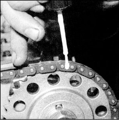 | 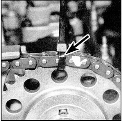 |
In order to maintain the mutual orientation of the sprocket and chain, it is advisable to put marks of mutual orientation on each of the sprockets and on the chain, tie the sprockets to the chain and ensure reliable mutual fixation, see figure (the arrow indicates the strapping with an insulating tube).
This method requires special care, but should greatly facilitate the work of the car owner, since there is no need to remove the cover of the timing chain drive.
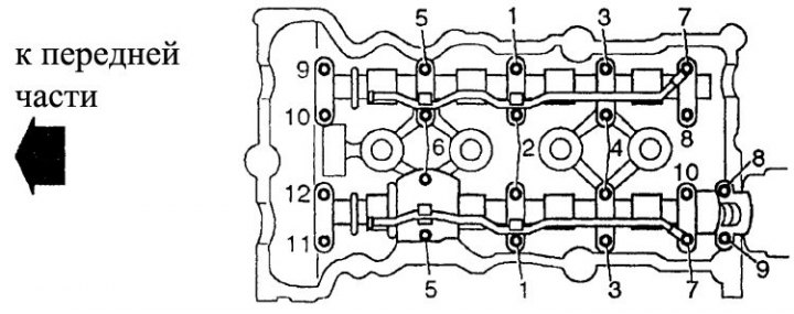
Bolt tightening sequence for bearing journals
Removing
1. Remove the ignition distributor (see subsection 7.7.4).
2. Remove the chain and camshaft driven sprockets (see subsection 3.2.1.7). If the chain remains on the engine, then mark the relative orientation (in fig. Relative orientation marks) and loosen the sprocket bolts (see clause 9 of subsection 3.2.1.7).
3. All camshaft journal covers are the same except for the front (right) exhaust camshaft covers. Therefore, before removing the covers, it is necessary to put identification marks on them.
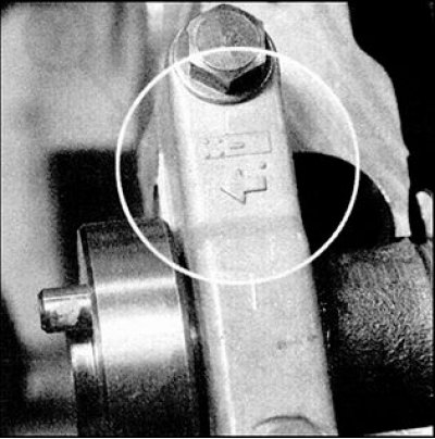
4. An arrow is molded into the top of the caps to indicate the correct orientation of the cap during assembly (all arrows must point towards the chain). The intake and exhaust camshafts have distinctive markings - "I" on the intake camshaft and "E" at the graduation booth.
5. Using a marker or scriber, number all the covers in order, starting from the front ones located on the side of the chain. This measure ensures that the covers are installed in their original places during assembly.
6. Loosen the camshaft bearing cap bolts by working in the reverse order to that shown in fig. Bolt tightening sequence for bearing journals.
7. Loosen the bolts in several steps, one turn at a time. This is necessary for a uniform and gradual weakening of the forces from the valve springs acting on the covers. After the springs are completely released, the bolts can be completely unscrewed. The cap bolts are divided by length into three size groups, therefore, remember the location of the cap bolts as they are unscrewed.
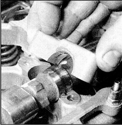
8. Remove the oil supply pipe from the covers of the bearing necks, and remove the oil deflector plate from the 2nd cover. Remove the exhaust camshaft covers, then remove the camshaft itself.
9. Repeat the steps according to paragraphs. 6–8 and remove the intake camshaft covers, then remove the camshaft itself (be aware that these caps do not have a flinger plate).
Status check
1. Inspect the surfaces in contact with the bearing journals of the camshafts, in the covers and in the cylinder head. Check the surfaces for burrs and signs of deep wear. Check for metal chipping on the camshaft cams (areas of bluish tint), deep workings, chips, flat areas formed due to wear.
2. Install the camshaft in the prismatic bearings and use a dial indicator to check the runout in the middle neck. If the runout is greater than normal, replace the camshaft.
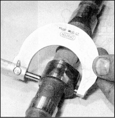
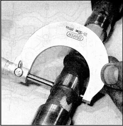
3. Using a micrometer, measure the size of each of the camshaft cams and compare the results with those indicated in subsection 3.2.1.1. If signs of damage are found or if excessive wear occurs, replace the camshaft.
4. Now check the clearance in the camshaft bearing journals. This can be done in two ways, either by direct measurement or by using the plastic Plastigage gauge.
5. When measuring the clearance directly, install the camshaft bearing caps into the cylinder head, according to the marks made before disassembly, so as not to disturb the previous order and orientation. Install the oil supply pipe and tighten the cap bolts to the specified torque in the sequence shown in Fig. Bolt tightening sequence for bearing journals. Measure the inner diameter of the bearing surfaces of the covers and compare with the indicated in subsection 3.2.1.1. If the inner diameter in any cover exceeds the limit, then replace the cylinder head.
6. The gap is defined as the difference between the inner diameter of the bearing surface of the cover and the diameter of the bearing neck.
7. When measuring clearance with the plastic Plastigage gauge, clean the camshafts and bearing surfaces of the journals in the cylinder head and in the covers with a clean, lint-free cloth. Lay the camshafts in the cylinder head.
8. Lay pieces of plastic gauge wire along the surfaces of the bearing journals of the camshafts parallel to their axis. Having taken measures to prevent the rotation of the camshafts, follow the steps described in paragraphs. 3–11 (see below), with the exception of the stage associated with the application of sealant to the covers.
9. Loosen the cover bolts (see point 6 above) and carefully remove the caps and the oil supply pipe without allowing the camshafts to rotate.
10. Compare the maximum width of the crushed wire from each neck with the scale on the gauge package and determine the gap.
11. Compare the measurement result with that specified in subsection 3.2.1.1. If the clearance is excessive, then measure the diameter of the camshaft bearing journal with a micrometer. If the diameter is less than the maximum allowable, then replace the camshaft and check the clearances in the bearing journals again. If the clearances are still too high, replace the cylinder head and bearing journal covers.
Installation
1. Make sure that each of the levers is correctly engaged with the corresponding hydraulic regulator and the guide disk installed on one of the valves that actuates the lever.
2. Liberally lubricate the bearing surfaces of the camshaft journals in the cylinder head with clean engine oil.
3. Install the camshafts in their positions in the cylinder head. The exhaust camshaft is easily identified by the slot on the left side for the ignition distributor drive.
4. Make sure the crankshaft is at TDC on the compression stroke (the groove on the toe of the crankshaft for the key must face vertically upwards when viewed from the right side of the engine).
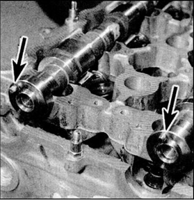
5. Install the camshafts in their positions in the cylinder head so that the cams of the 1st cylinder are facing away from the corresponding valves, orienting the pins on the ends (indicated by arrows). With the camshafts in the correct position, the locating pin of the intake camshaft sprocket at the front of the camshaft should point at 10 o'clock (viewed from the right side of the engine), and the exhaust camshaft pin must be in the upper vertical position.
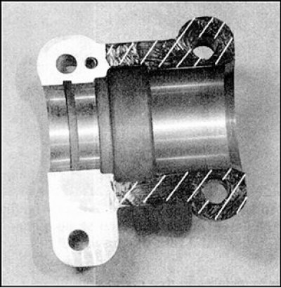
6. Make sure that the contact surfaces of the bearing neck covers and cylinder head beds are absolutely clean, that there are no foreign inclusions and traces of oil on these surfaces. Apply a light coat of sealant to the split surface of the leftmost exhaust camshaft cover marked with slanted hatching.
7. Install the bearing neck covers in the same order, guided by the marks made during disassembly.
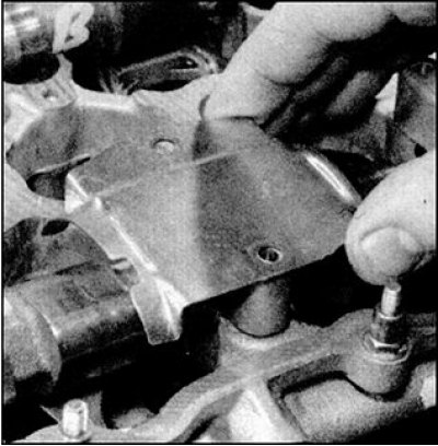
8. Install the oil baffle plate on the 2nd exhaust camshaft cover, install the oil supply pipe.
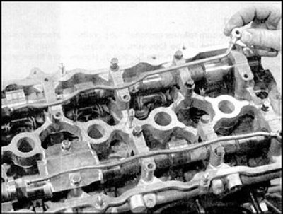
9. Then install the oil supply pipes, fixing them on the bolts of the bearing journals. Screw in the bolts of the bearing journals and hand-tighten.
10. Tighten the intake camshaft cover bolts in the sequence shown. Tighten the bolts evenly, gradually increasing the force, turning the bolts one turn at a time, until the covers come into contact with the cylinder head (see fig. Bolt tightening sequence for bearing journals). Then tighten the bolts to the specified torque. Tighten only in the order shown to ensure an even and gradual increase in force from the valve springs on the bearing journal covers.
11. Tighten the exhaust camshaft cap bolts by repeating the previous step.
12. Install the chain and camshaft sprockets (see subsection 3.2.1.7).
13. If the chain has not been removed, then put the sprockets on the corresponding camshafts, put on the chain, exactly aligning the marks on the chain and on the sprockets made before disassembly. Wrap the bolts of the asterisks, having previously put washers on them, tighten the bolts with a given moment.
14. Install the ignition distributor (see subsection 7.7.4).