Note.
This section contains procedures for removing and installing the camshaft with the engine front cover installed. If the engine front cover was previously removed, the following steps must be changed:
- Step 8: After removing the camshaft sprocket, remove the camshaft covers (№2-5).
- Step 9: The exhaust camshaft can be removed at the same time as the intake camshaft.
- Step 10: If the intake camshaft sprocket mounting bolt is removed, lifting the camshaft is not necessary.
1. Support the underside of the engine with a transmission jack, and then remove the engine mount bracket and right spring.
2. Remove the cylinder head cover (rocker cover).
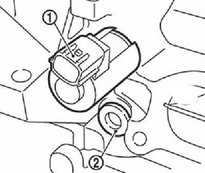
3. Remove the camshaft position sensor from the rear of the cylinder head.
Attention. Be careful not to strike the camshaft position sensor.
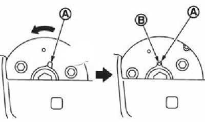
4. Set the piston of the first cylinder to the position of the top dead center of the compression stroke as follows:
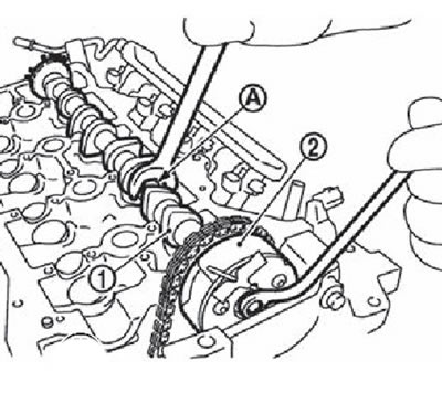
Rotate the crankshaft pulley (2) clockwise until the TDC mark is aligned (without color mark) (A) with pointer (1) on the front cover. white color mark (IN) not used for engine maintenance.

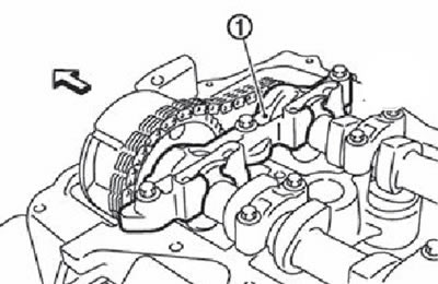
Make sure the timing marks on each camshaft sprocket are set as shown.
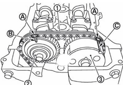
1. Timing chain drive.
2. An asterisk of a final camshaft.
3. Intake camshaft sprocket.
A. Installation mark (dye).
B. Installation mark (stamp).
C. Installation mark (lateral knurling).
Note. If the marks are not in the specified position, turn the crankshaft pulley one more turn to set the marks to the desired position.
Apply paint marks on the drive chain links.
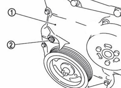
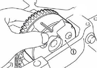
5. Lock the chain tensioner plunger in the fully compressed position as follows (then release the chain tensioner):
Remove cork (2) from the front cover (1).
Press the lever all the way (IN) chain tensioner (2) through the hole in the front cover, then insert the locking pin (A) into the side hole of the cylinder block and fix the lever in the lower position.
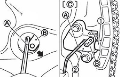
A. Locking pin.
B. Tensioner lever.
C. Shown with front engine cover removed.
Note.
- The tongue is released by fully pressing the lever, as a result of which the plunger (1) can move again.
- The illustration shows the use of a 2.5 mm hexagon as an example.
Attention. The locking pin must have a curve to prevent the pin from accidentally falling under the engine front cover.
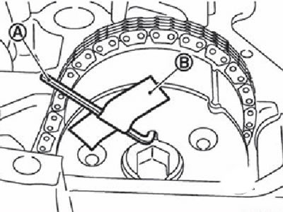
Rotate the crankshaft pulley (2) counterclockwise strtlkk, fixing the camshaft (1) for the hexagon (A) wrench. Having thus tensioned the drive chain, press the plunger into the tensioner.
Remove lock pin from tensioner (2). Pulling the lever (IN), align the hole in it with the hole in the body. When the lever hole (WITH) coincides with the hole in the body, the plunger (1) fixed. If the protrusions of the plunger ratchet and tongue are opposite each other, the holes do not line up. At this point, it is necessary to hook them correctly and align the holes by slightly moving the plunger.
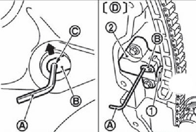
A. Locking pin.
B. Tensioner lever.
C. Lever hole.
D. Shown with engine front cover removed.
Insert the locking pin into the body hole through the lever hole, then fix the lever in the up position.
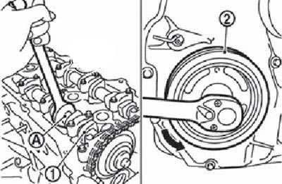
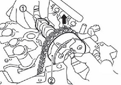
Slightly turn the crankshaft pulley (2) clockwise to loosen the drive chain on the side of the exhaust camshaft sprocket (1).
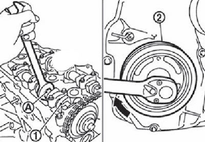
Attention. To fix the camshaft, hold it with a wrench on the hexagonal part (A).
6. Remove the exhaust camshaft sprocket (1).
Attention.
- Holding the camshaft by the hex part (A), fix it.
- Do not turn the crankshaft or camshaft separately from each other to avoid damage to the piston by the valves in the future.
Note. If the front cover is installed on the engine, the drive chain does not disengage from the crankshaft sprocket and fall into the front cover. Therefore, it is not necessary to use a drive chain retainer.
7. Turn the intake camshaft sprocket all the way forward.
Attention.
- Installation and removal of the intake camshaft sprocket should be carried out in the position of the extreme stop possible for the following reasons:
- Star (WITH) and blades (camshaft clutch) (IN) are designed to rotate and move within a range of a certain angle. When the engine is stopped and the blade angle is reduced as much as possible, rotation will not occur due to the fact that the blades are blocked on the sprocket side by an internal pin (A). If the camshaft sprocket bolts are rotated in this situation, the lock pin may be damaged, causing failure due to increased horizontal load (shear force) on the stop pin.
Loosen the mounting bolts in several steps and remove the camshaft cover (necks №1) (1).
Note. The arrow points to the front of the engine.
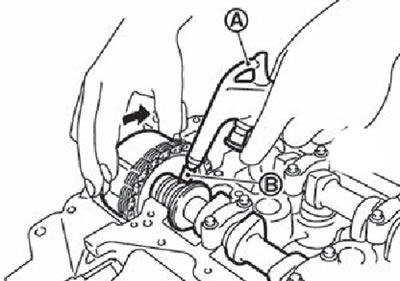
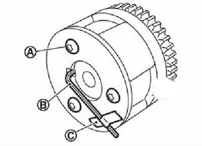
Supply compressed air (under pressure 300 kPa (3.1 kg/cm2) or more) into the oil hole (A) root support No. 1 (on the second recess from the front thrust washer (IN)) intake camshaft (1), as it shown on the picture.
Note. The next step is carried out with a constant supply of compressed air.
Connect rubber tip (IN) tapered to the top of the air gun (A) to prevent air leakage from the oil hole. Apply compressed air.
Attention.
- There are other lubrication holes on the side of the groove. Only supply air to the lubrication hole described above.
- Make sure the oil groove is not damaged by the tip of the air gun.
- Before applying air, remove all oil from the tip of the air gun to prevent oil splashing later. Eye protection must also be worn (glasses).
Note. The compressed air supply is used to move the locking pin into the unlock position.
While holding the intake camshaft sprocket with your hands, apply a clockwise or counterclockwise force of your choice, and then rotate the intake camshaft sprocket counterclockwise (direction of rotation indicated by the arrow in the figure).
If the lock pin cannot be released manually, tap the intake camshaft sprocket lightly with a plastic mallet (A).
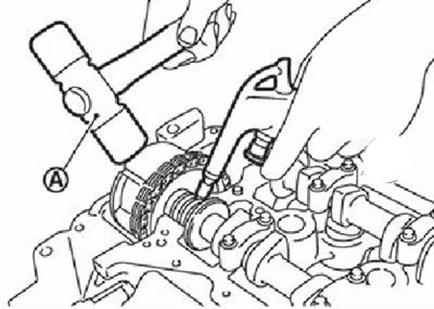
If the intake camshaft sprocket does not rotate counterclockwise even after performing the above procedures, check the air pressure for the position of the oil port.
Performing the above operations, as soon as a click is heard from inside the intake camshaft sprocket (internal locking pin unlock sound), start turning the sprocket counterclockwise until it stops.
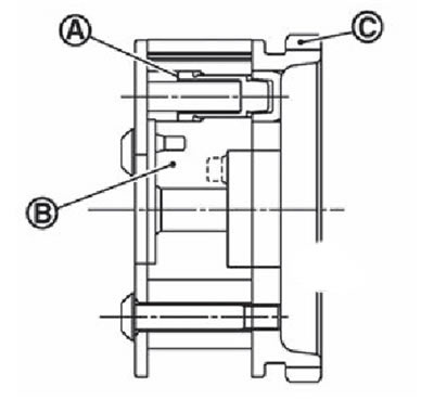
A. Lock pin groove.
B. Locking pin hole.
C. Extreme minimum corner position (lock pin locked).
D. Extreme maximum position of the corner.
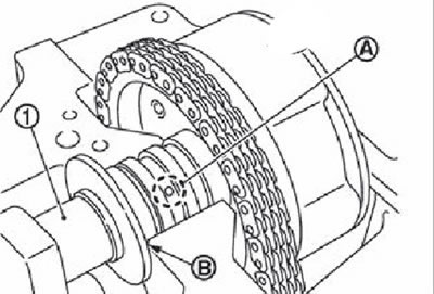
Apply compressed air. If there is no click, the locking pin is unlocked as soon as the side of the blades (camshaft side) begins to rotate independently of the sprocket.
Verify that the coupling is at the extreme maximum angle position by whether the groove of the locking pin is aligned (A) with locking pin hole (IN) as it shown on the picture.
Shut off the compressed air supply and unlock the intake camshaft.
Insert locking pin (A) into the corresponding hole in the intake camshaft sprocket and fix the sprocket in the maximum position,
Attention. Do not apply force to the locking pin (spring resistance etc.). Since the hairpin (A) while it is not fixed and can easily fall out, it is necessary to use electrical tape or adhesive tape (IN) to fix it.
Note. As a locking pin, for example, a 2.5 mm hexagon with an insertion length of approximately 15 mm can be used.
8. Remove the camshaft covers (№ 2-5).
Note. Loosen the bolts in several passes in the reverse order shown in the figure.
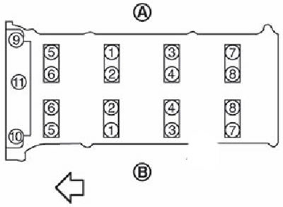
A. Release side
B. Inlet side
Note.
- The arrow in the figure points to the front of the engine.
- Camshaft cover (№1) by this time already removed.
9. Remove the final camshaft.
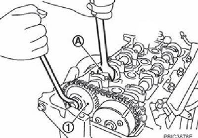
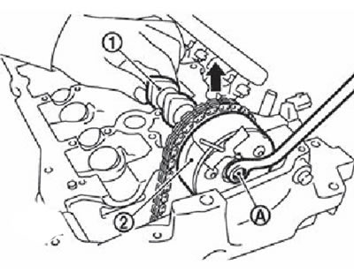
10. Remove intake camshaft (1) with an asterisk (2) in the following way:
Raise the intake camshaft sprocket and install a thin tool (box wrench) on fixing bolt (A).
Reinstall the intake camshaft into the cylinder head bearings.
Holding the hex part (A) wrench, unscrew the bolt securing the intake camshaft sprocket (2).
1. Intake camshaft.
2. Intake camshaft sprocket.
Raise intake camshaft (1) and separate the camshaft and sprocket (2).
Remove the camshaft back.
Attention. Take care not to damage the impulse disc at the rear of the camshaft.
Remove intake camshaft sprocket (1).
Attention.
- Be careful not to drop the locking pin
- Glue lock pin (IN) tape (WITH), so that it doesn't fall out.
- Be careful not to drop the camshaft sprocket with phase shifter. Do not disassemble the phase shifter (do not loosen the three mounting bolts (A)).
Note.
If, when removing the intake camshaft sprocket, the locking pin falls out and the stud is displaced, the following must be done:
- Install the intake camshaft and tighten the mounting bolts to prevent compressed air leaks.
- Apply compressed air to unlock the locking pin and rotate the coupling to its maximum position.
- Insert locking pin.
- Remove the sprocket from the intake camshaft.
Attention. The internal locking pin can be damaged, so the fastening bolts must be tightened to a minimum torque.
11. Mark the positions of the pushers and remove them, arranging them in order without mixing.
12. Remove the intake valve opening control solenoid valve (1).
13. Remove the generator with the bracket, remove the plug (2), and then remove the oil filter.