Attention. The direction of rotation referred to below is seen from the front of the engine.
1. Remove the front right wheel.
2. Remove the right fender liner.
3. Drain engine oil.
Attention. Perform this step only on a cold engine.
4. Remove the following parts:
- Intake manifold.
- Attachment drive belt.
- Water pump pulley.
- Right ground cable.
5. Support the underside of the engine with a transmission jack, and then remove the engine mount bracket and right spring.
6. Remove rocker cover.
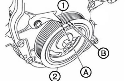
7. Set the piston of the first cylinder to the top dead center position of the compression stroke as follows:
- Rotate the crankshaft pulley (2) clockwise until the TDC mark is aligned (without color mark) (A) with pointer (1) on the front cover. white color label (IN) not used for engine maintenance.
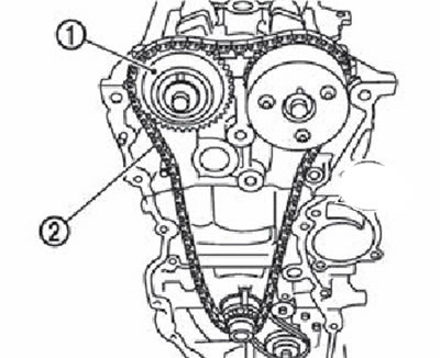
- Make sure that the timing marks of each camshaft sprocket are set as shown in the illustration.
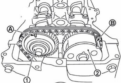
1. An asterisk of a final camshaft.
2. Intake camshaft sprocket.
A. Installation mark (stamp).
B. Installation mark (lateral groove).
Note. If the marks are not in the specified position, turn the crankshaft pulley one more turn to set the marks to the desired position.
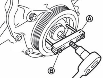
8. Remove the crankshaft pulley as follows:
Fix the crankshaft pulley (1), using a suitable tool (A).
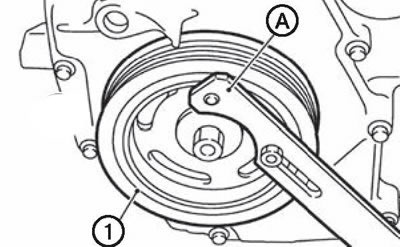
Loosen the crankshaft pulley bolts.
Attention. Do not remove the crankshaft pulley bolts as they are used as studs for the pulley puller.
Install the puller (KV11103000) (A) opposite threaded holes for bolts MB (IN) on the pulleys, l then remove the crankshaft pulley.
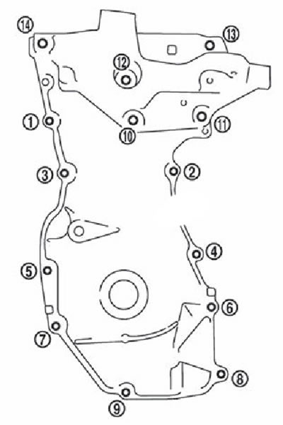
9. Remove the engine front cover as follows:
Loosen the screws in the reverse order to that shown in the figure.
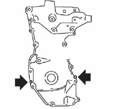
Cut the thermetic in the tone indicated by the arrow in the figure, and then remove the front engine cover.
10. Using a suitable tool, remove the front crankshaft oil seal from the front cover.
Attention. Be careful not to damage the front cover.
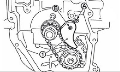
11. Remove chain tensioner (1):
Fully hedgehog tensioner arm (A), then press the plunger (WITH) inside the tensioner. tongue (IN) is released by fully pressing the lever, as a result of which the plunger can move again.
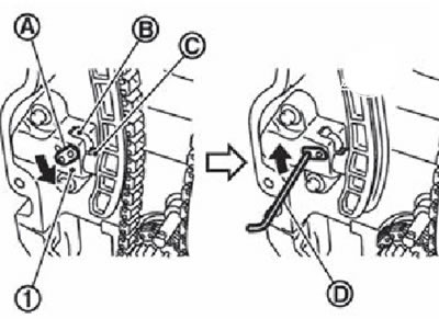
Pulling the lever, align the hole in it with the hole in the body. When the hole in the lever matches the hole in the body, the plunger is fixed. If the protrusions of the plunger ratchet and tongue are opposite each other, the holes do not line up. At this point, it is necessary to hook them correctly and align the holes by slightly moving the plunger.
Insert locking pin (D) into the housing hole through the lever hole, then fix the lever in the upper position. The illustration shows the use of a 2.5 mm hexagon as an example.
Remove chain tensioner.
12. Remove damper (2) and drive chain tensioner shoe.
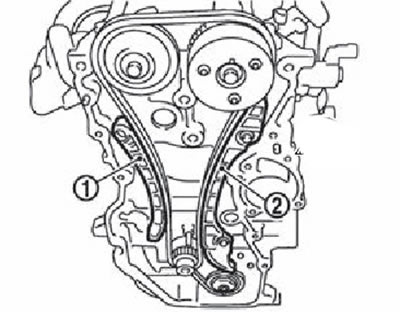
13. Remove the timing chain (2). By pulling the slack part of the drive chain towards the exhaust camshaft sprocket (1), remove the chain starting at the exhaust camshaft sprocket side.
Attention. Do not rotate the crankshaft or camshafts after removing the timing chain. This can cause damage to valves and pistons due to mutual contact.
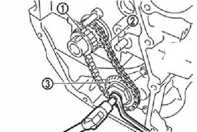
14. Remove the crankshaft sprocket and oil pump drive parts:
Remove chain tensioner (1), by pulling it off the axis (IN) spring lock holes (A).
Holding the top of the oil pump shaft with a TORX socket (size: E8), loosen and remove the oil pump sprocket nuts.
Remove the crankshaft sprocket at the same time (1), oil pump drive chain (2) and oil pump sprocket (3).