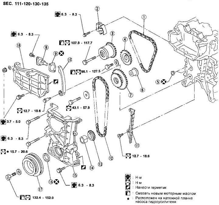
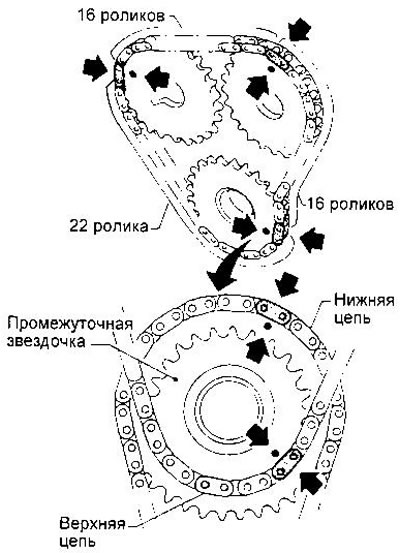
1. Top drive chain
2. Upper chain tensioner
3. Inlet camshaft drive sprocket with variable valve timing mechanism
4. Exhaust camshaft drive sprocket
5. O-ring
6. Intermediate sprocket shaft
7. Intermediate sprocket
8. Lower drive chain tensioner
9. Gasket
10. Tensioner shoe
11. Appreciate the calmer
12. Lower drive chain
13. Crankshaft sprocket
14. Oil pump drive spacer
15. Front crankcase
16. Front crankshaft oil seal
17. Crankshaft pulley
18. Front cylinder head cover
Removing
WARNINGS:
- After removing the drive chain, do not turn the crankshaft and camshaft separately, so as not to damage the pistons and valves.
- When installing the camshaft, chain tensioner, oil seals and other parts that have friction surfaces, lubricate them with new engine oil.
NOTE: The illustration shows an actuator with variable valve timing (VTC — Valve Timing Control). In the absence of phase and position adjustment (3) a conventional sprocket is installed, which is fastened with a bolt with a tightening torque of 98.2-127.5 Nm. In this case, the front cover of the cylinder head has a different shape, the tightening torques of its fixing bolts do not change.
When installing the cylinder head, drive sprockets and camshaft bearing caps, apply engine oil to the threads and seating surfaces of the bolts.
1. Drain the coolant from the radiator and cylinder block. Be careful not to get liquid on the drive belts.
2. Relieve pressure in the supply system (see chapter «fuel injection system»).
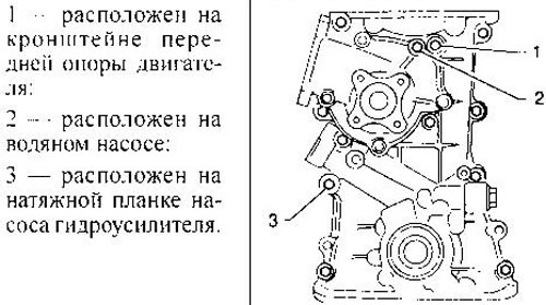
3. Remove the power steering pump and generator.
4. Remove the power steering pump pulley and the pump itself with the bracket.
5. Disconnect the air line from the intake manifold.
6. Remove the front right wheel.
7. Remove the front mudguards of the engine.
8. Remove a reception pipe of final system.
9. Remove the front bracket of the cylinder head.
10. Remove the cylinder head cover and ignition distributor cover.
11. Remove all spark plugs.
12. Remove the intake manifold bracket.
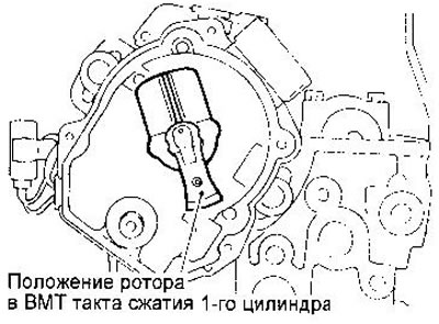
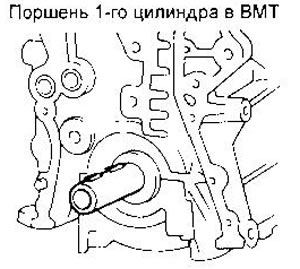
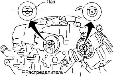
13. Set the piston of the 1st cylinder to the TDC of the compression stroke. Check the installation of the piston on the distributor rotor.
14. Remove the distributor of ignition.
15. Remove the water pump drive pulley.
16. Remove the thermostat housing.
17. Remove the lower chain tensioner, then the upper chain tensioner.
18. Loosen the intermediate sprocket mounting bolt, then unscrew the camshaft drive sprocket mounting bolts and remove the sprockets.
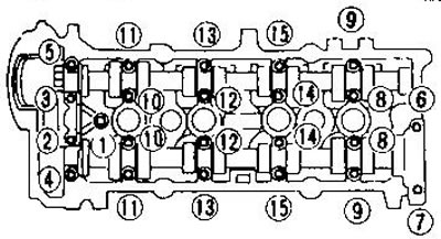
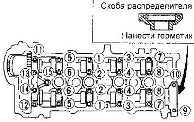
19. Remove the camshaft bearing caps, and then the shafts themselves. These parts must be installed in their original places during assembly. Cover bolts should be loosened in two or three steps, in the sequence shown in the figure.
20. Turn away a bolt of an intermediate asterisk.
21. Remove the cylinder head with manifolds. The bolts should be loosened in two or three steps, in the reverse order of tightening. Otherwise, the cylinder head may be deformed or cracked.
22. Remove the intermediate sprocket shaft from the rear.
23. Remove the top drive chain.
24. Remove the center beam, then remove the oil pan (see previous section) and may l about the receiver.
25. Remove the crankshaft pulley.
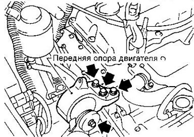
26. Place a jack under the engine (or raise his waist) and remove the front engine mount.
27.Remove the front support bracket.
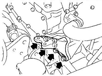
28. Remove the front crankcase by unscrewing the following bolts:
29. Remove intermediate bushing and lower drive chain
30. Remove the oil pump spacer.
31. Remove the tensioner shoe «lower chain damper.
32. Remove the crankshaft sprocket.
Installation
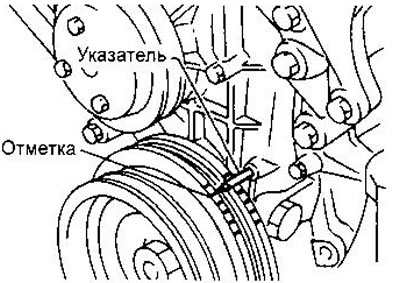
1. The crankshaft must be installed in the position corresponding to the TDC of the compression stroke of the 1st cylinder.
2. Install the crankshaft sprocket and oil pump drive spacer. The marks on the sprocket should point away from the motors.
3. Install the tensioner shoe and lower chain guide.
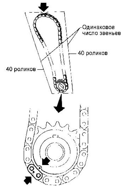
4. Put on the lower drive chain. The mark on the chain must match the mark on the crankshaft sprocket.
The number of links between the marks on the chain is the same on the right and left. The chain can be installed in either direction.
5. Before installing the front crankcase, remove all traces of old sealant from the mounting surfaces of the crankcase and cylinder block.
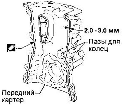
6. Install the front crankcase, applying sealant as a gasket.
Check the alignment of the marks on the chain and crankshaft sprocket.
Align the spacer with the oil pump.
Press the chain against the tensioner shoe and guide so that it cannot hit the front crankcase water passage.
Make sure there are two o-rings. When installing the front crankcase, be careful not to damage the crankshaft oil seal.
7. Establish an arm of a forward support of the engine and a support.
8. Install the oil receiver and oil pan.
9. Install the crankshaft pulley.
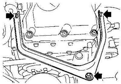
10. Install the center beam.
11. Install the intermediate sprocket, matching the marks on the large sprocket and the lower drive chain.
12. Place the upper drive chain on the intermediate sprocket, aligning the marks on the chain and small sprocket. The marks on the sprockets should point away from the engine.
13. Install the intermediate sprocket shaft from the rear.
14.Install the cylinder head.
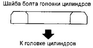
Make sure washers are installed under the cylinder head bolts.
Apply new engine oil to the threads and seating surfaces of the cylinder head bolts.
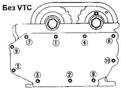
Tightening sequence:
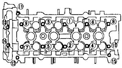
a) Tighten bolts 1-10 in the sequence shown in the figure to a torque of 29.4 Nm.
b) Tighten bolts 1-10 to 58.8 Nm.
c) Completely loosen the bolts in reverse order.
d) Tighten bolts 1-10 again to 29.4 Nm.
e) Tighten bolts 1-10 by 50-55°, or, in the absence of a wrench with a goniometer, tighten them to a torque of 58.8±4.9 Nm.
f) Tighten bolts 11-15 to 6.3-8.3 Nm.
15. Wrap a bolt of fastening of an intermediate asterisk.
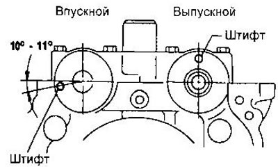
16. Install camshafts. The shafts must be installed in the position shown in the figure. To identify the shafts, they are marked I (inlet) and E (high school graduation).
17. Establish covers of bearings of camshafts and distributor bracket.
The covers must be oriented as shown in the figure.
Before installing the distributor bracket, apply sealant to its mounting surface.
Apply new engine oil to the threads and mounting surfaces of the bolts.
Bolt tightening sequence (bolt 15 is present only in the GA16DE engine):
- a) Tighten bolts 11-15, then 1-10 in the sequence shown in the figure to a torque of 2.0 Nm.
- b) Tighten bolts 1-15 to 5.9 Nm.
- c) Tighten bolts 1-14 to 9.8-11.8 Nm, then bolt 15 to 6.3-8.3 Nm.
After reassembly, check and, if necessary, adjust the valve clearances (see section «valve clearances»).
18. Put on the upper drive chain on the sprockets, aligning the alignment marks. The marks on the sprockets should point away from the engine.
19. Wrap bolts of fastening of driving sprockets of camshafts, having previously applied new engine oil on their carving and landing surfaces.
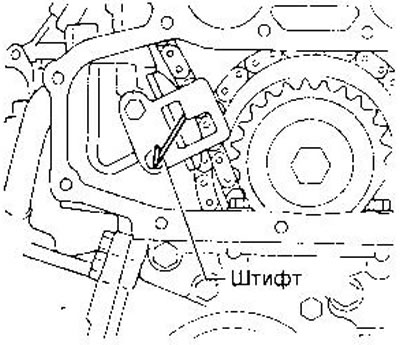
20. Install the upper drive chain tensioner.
Before installing the tensioner, insert a suitable pin into its hole, as shown in the figure. Remove the pin after installing the tensioner.
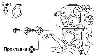
21. Install the lower chain tensioner. Pay attention to the orientation of the gasket.
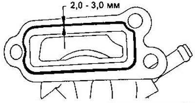
22. Install the thermostat housing by applying sealant to the mounting surface.
23. Install the water pump pulley.
24. Install the distributor, making sure that the camshaft is in the correct position.
25. Establish a forward cover of a head of cylinders, having previously applied sealant on its mounting surface.
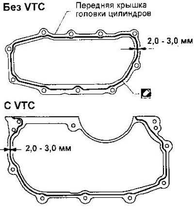
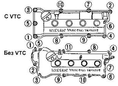
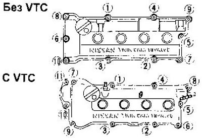
Tighten the bolts and nuts in the sequence shown.
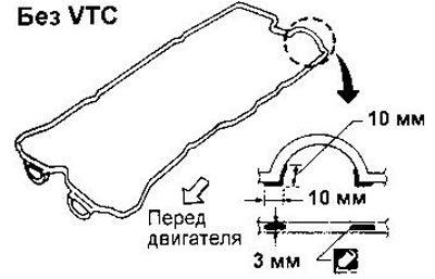
Without VTC:
26. Apply sealant to the cylinder head.
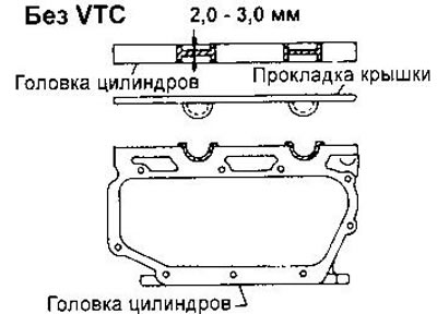
27. Apply sealant to the cylinder head cover gasket.
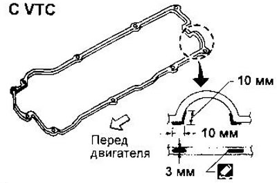
From VTC:
26. Apply sealant to the joint between the cylinder head and the front cover of the cylinder head.
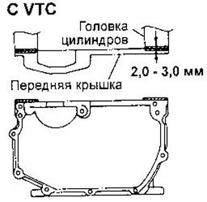
27. Apply sealant to the cylinder head cover gasket.
28. Establish a cover of a head of cylinders and tighten bolts in the sequence specified in drawing.
29. Install spark plugs.
30. Install the engine front mount bracket and front mount.
31. Attach a reception pipe of final system.
32. Install engine mudguards.
33.Install the right wheel.
34. Connect the air line.
35. Install the power steering pump pulley and the pump itself with the bracket.
36. Put on the drive belts and adjust their tension as described in the chapter «Maintenance».