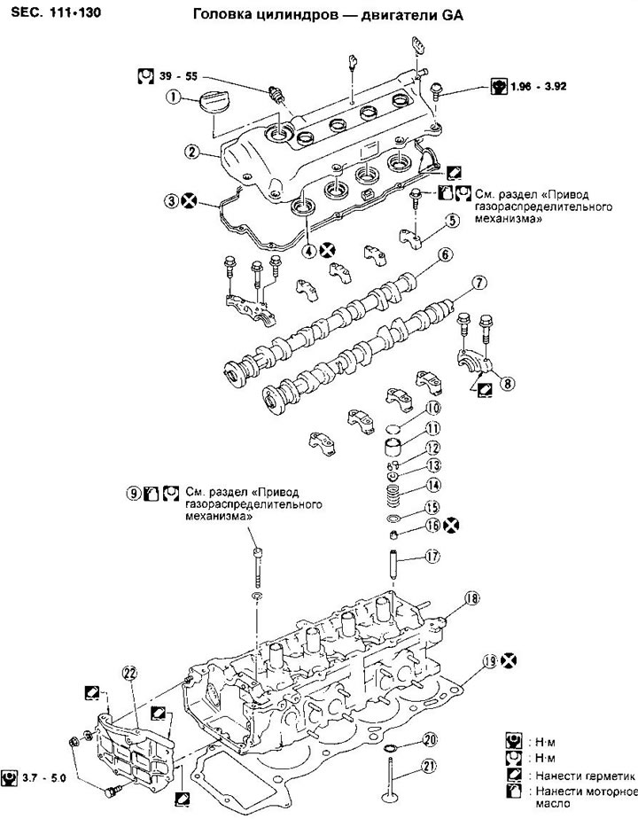
1. Filler cap
2. Cylinder head cover
3. Cylinder head cover gasket
4. Oil seal
5. Camshaft bearing cap
6. Inlet camshaft
7. Exhaust camshaft
8. Ignition distributor bracket
9. Cylinder head bolt
10. Adjusting washer
11. Valve lifter
12. Rusk
13. Spring plate
14. Valve spring
15. Valve spring seat
16. Oil cap
17. Valve guide
18. Cylinder head
19. Cylinder head gasket
20. Valve seat
21. Valve
22. Front cylinder head cover
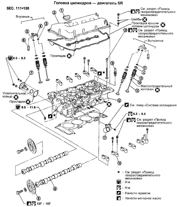
1. Filler cap
2. Cylinder head cover
3. Lever guide
4. Valve lever
5. Adjusting washer
6. Hydraulic gap compensator
7. Drive chain tensioner
8. Camshaft drive sprocket
9. Camshaft
10. Camshaft bearing cap
11. Water connection
12. Cylinder head
13. Valve
14. Valve spring seat
15. Valve spring
16. Valve spring plate
17. Rusk
18. Spark plug
19. Cylinder head bolt
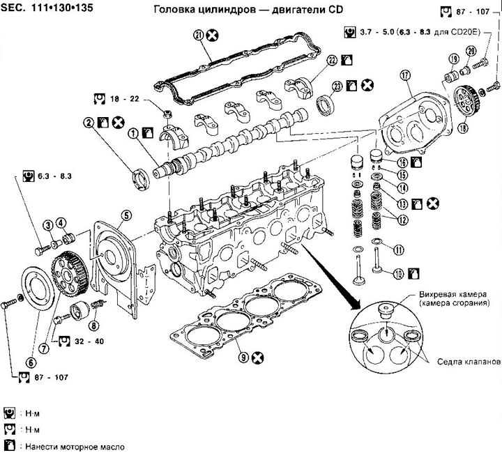
1. Camshaft
2. Front camshaft oil seal
3. Distance sleeve
4. Rubber bushing
5. Front cover
6. Toothed belt guide
7. Front camshaft sprocket
8. Tension roller spring
9. Cylinder head gasket
10. Valve
11. Valve spring seat
12. Valve spring
13. Oil cap
14. Spring plate (inlet valve) or valve rotator (Exhaust valve)
15. Rusk
16. Hydraulic pusher
17. Back cover
18. Rear camshaft sprocket
19. Rubber bushing
20. Distance sleeve
21. Cylinder head cover gasket
22. Camshaft bearing cap
23. Rear camshaft oil seal
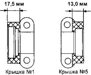
NOTE: The rear cover has a different shape on the CD20E engine due to the installation of a vacuum pump.
Removal and installation - GA and SR engines
Removal and installation of a head of cylinders are described in the section «Timing gear drive».
Disassembly - GA Engines
1. Remove the valves using a spring compression tool.
2. Remove the oil seals (see section «Replacement of oil seals»).
Disassembly - SR engine
WARNINGS:
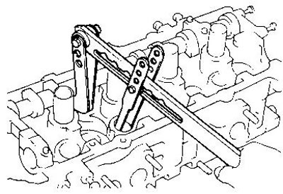
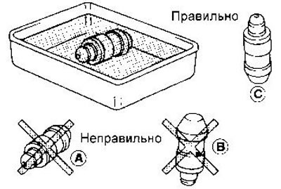
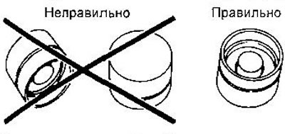
- If the hydraulic lash adjusters are horizontal, air can enter them. Once removed, keep the lifters upright or soak them in a bath of new engine oil.
- Do not disassemble hydraulic lifters.
- Mark the hydraulic lifters so that they can be installed in their original places during assembly.
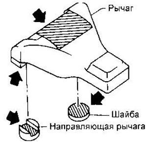
1. Remove the valve actuation levers, shims, lever guides and hydraulic lash adjusters.
When assembling, all parts must be installed in their original places.
2. Remove the crankcase ventilation oil separator.
3. Remove the exhaust manifold cover.
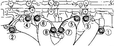
4. Remove the exhaust manifold following the nuts loosening sequence shown in the figure.
5. Remove the water pipe.
6. Remove the intake manifold brackets.
7. Remove the fuel rail with injectors (see chapter «Engine management system»).
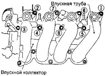
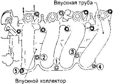
8. Remove the intake manifold, observing the sequence of unscrewing the nuts shown in the figure.
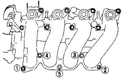
9. Disconnect inlet pipes from a collector, loosening nuts in the sequence specified in drawing.
10. Remove the thermostat housing along with the water hoses.
11. Remove the valves using a special tool or equivalent to compress the springs.
12. Remove the oil seals with pliers.
Removal - CD Engines
1. Drain the coolant and disconnect the downpipe from the exhaust manifold.
2. Disconnect the water hoses, air line and remove the intake manifold.
3. Remove heat shield and exhaust manifold.
4. Remove the cylinder head cover and injectors.
5. Remove both toothed belts.
After removing the belts, do not turn the crankshaft and camshaft separately, so as not to damage the pistons and valves.
6. Remove a head of cylinders, observing the sequence of easing of bolts specified in drawing.
Disassembly - CD Engines
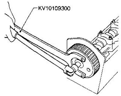
1. Remove the timing belt guide from the front camshaft pulley, then remove the front and rear pulleys using a special wrench and the rear cover.
2. Remove the camshaft bearing caps, starting with the inner ones. Loosen the nuts in two or three steps.
3. Remove the camshaft and seals.
4. Remove the valve lifters.
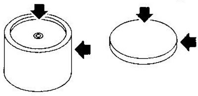
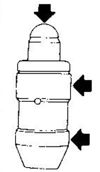
- Do not hold the hydraulic tappets as shown in the figure to avoid getting air into them.
- Do not disassemble hydraulic tappets.
- After removal, mark the pushers to install them in their original places.
- After removal, the tappets should be placed in engine oil.
5. Remove the valves using a special tool or equivalent to compress the springs.
During assembly, all parts of the valves must be installed in their original places.
6. Remove the oil seals using the special tool KV10107902.
Check and repair
Deformation of the cylinder head. Clean the mating surface of the cylinder head. Use a metal ruler and a feeler gauge to check if the flatness is within tolerance.
The test must be carried out in 6 directions as shown in the figure.
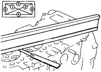
Flatness deviation:
- Nominal - no more than 0.03 mm
- Maximum allowable - 0.1 mm
Flatness in at least one of the directions exceeds the allowable limit, replace or regrind the cylinder head.
The maximum reduction in the height of the cylinder head is determined from the condition A + B = 0.2 mm (0.1 mm for CD motors), where A is the reduction in the height of the cylinder head, B is the reduction in the height of the cylinder block after processing.
After grinding the cylinder head, the camshaft must be free to rotate by hand. If resistance is felt, the cylinder head must be replaced.
Nominal cylinder head height:
- GA Engines - 117.8-118.0mm
- SR Engine - 136.9-137.1mm
- CD Engines - 137.9-138.1mm
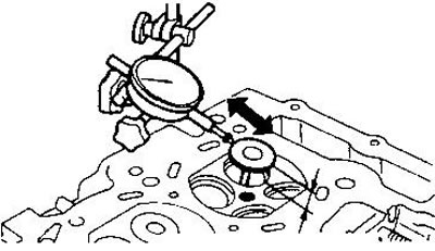
General condition of the camshaft. Check the shaft for scratches, nicks and visible wear. Camshaft beat. Measure the runout along the center journal, determining the maximum difference in the indicator readings per 1 revolution.
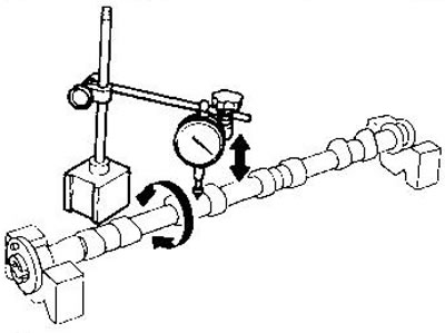
- Rated runout - no more than 0.02 mm
Maximum allowable runout:
- GA and SR motors - 0.1mm
- CD motors - 0.05mm
If the runout exceeds the allowable limit, replace the camshaft.
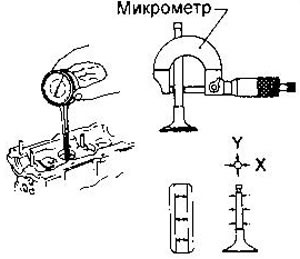
Camshaft lobe height
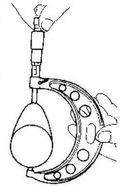
Measure the camshaft lobe height with a micrometer.
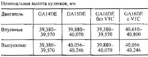
The wear limit for GA and SR motors is 0.2 mm. For CD motors, the cam height must be within the limits shown below. If wear exceeds allowable values, replace the camshaft.
Nominal jaw height for SR20DE (from 04.96):
- Inlet 38.408-38.598 (37,989-38,179) mm
- Graduation 37,920-38,110 (37,309-37,499) mm
Nominal jaw height for CD20 (CD20E):
- Inlet - 49.20-49.25 (48,70-18,75) mm
- Graduation - 49.15-49.20 (49,15-49,20) mm
Diametral clearance in the camshaft bearings. Install the camshaft bearing caps and tighten the bolts to the correct torque. Measure the inside diameter of the bearings.
Nominal inside diameter for GA motors:
- Bearing #1 - 28.000-28.021 mm
- Bearings #2-5 - 24.000-24.021 mm
Nominal bore for SR motor:
- All bearings - 28.000-28.021 mm
Nominal inner diameter for CD motors:
- All bearings - 30.000-30.021 mm
Measure the diameter of the camshaft journals. Nominal journal diameter for GA motors:
- Neck No. 1 - 27.935-27.955 mm
- Necks No. 2-5 - 23.935-23.955 mm
Nominal journal diameter for SR motor:
- All necks - 27.935-27.955 mm
Nominal journal diameter for CD motors:
- All necks - 29.935-29.955 mm
If the bearing clearance exceeds the limit below, replace the camshaft and/or cylinder head.
- Nominal clearance - 0.045-0.086 mm
Maximum allowable clearance:
- GA and SR motors - 0.15mm
- CD motors - 0.1mm
Axial clearance of the camshaft. Install the camshaft in the cylinder head and measure the axial movement of the shaft.
Nominal clearance, mm:
- GA 16DE without VTC and GAI4DE - 0.070-0.143
- GA16DE with VTC and GA15DE - 0.115-0.188
- SR engine - 0.055-0.139
- CD engines - 0.115-0.188
Maximum allowable (GA and SR) — 0,20
For CD motors, the clearance must be within the above limits.
Runout of sprockets of camshafts (C A and SR engines). Install the sprocket onto the camshaft and measure runout with a dial gauge.
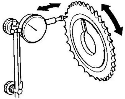
The difference in indicator readings per shaft revolution should not exceed 0.1 mm for GA motors and 0.25 mm for SR motors.
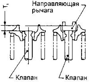
Gap between valves and guide bushings. Measure the valve play in a direction perpendicular to its axis. In this case, the distance from the valve disc to the valve seat should be about 25 mm for GA engines and about 15 mm for SR and CD engines.
Maximum allowable backlash, mm:
- GA and SR engines - 0.2
- CD engines - 0.1
If the backlash exceeds the specified limit, check the clearance between the valve and the guide sleeve by measuring the inner diameter of the sleeve and the outer diameter of the valve stem.
Nominal clearance for inlet valves, mm:
- GA and CD engines - 0.020-0.050
- SR engines - 0.020-0.053
Nominal clearance for exhaust valves:
- GA and CD engines - 0.040-0.070
- SR engines - 0.040-0.073
Maximum allowable clearance, mm:
- Engine intake valves SR - 0.08
- The rest - 0.1
If the clearance exceeds the limit, replace the valve or guide sleeve.
Replacing valve guides
1. Heat the cylinder head in an oil bath to 110-120°C (GA and SR engines) or 150-160°С (cd engines).
2. Drive out the guide bushing with a hammer and a suitable drift.
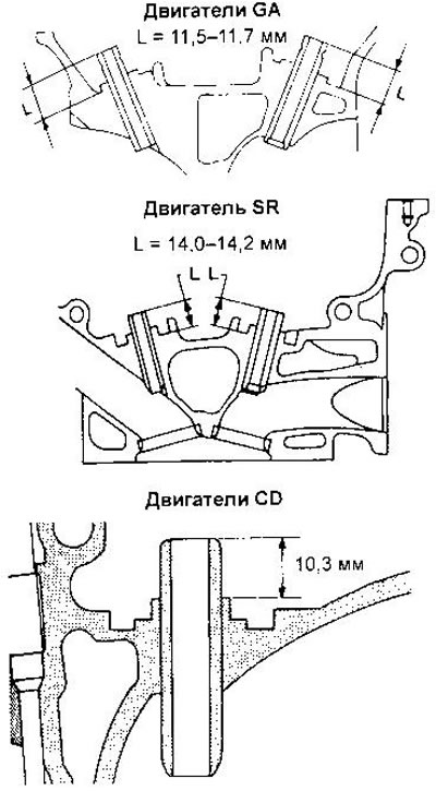
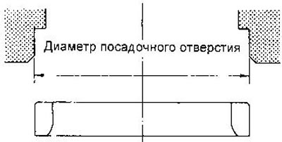
3. Expand the hole in the cylinder head for the oversized guide bushing (the holes for the inlet and exhaust valve bushings have the same diameter).
Hole diameter for guide bushing, mm:
- GA engines - 9.685-9.696
- Engine SR - 10.175-10.196
- CD Engines - 11.185-11.196
4. Press in the new bushing by heating the cylinder head to the same temperature as when pressing the old bushing.
5. Unroll the new guide bushing. The internal diameters of the bushings for the inlet and outlet valves are the same.
Final Diameter:
- GA Engines - 5.500-5.515mm
- SR Engine - 6,000-6,018mm
- CD Engines - 7,000-7,015mm
Valve repair and replacement. Valve seats must be repaired or replaced if there is pitting, corrosion, damage and visible wear on the working faces.
Before repairing seats, inspect valves and guides. Replace parts worn beyond acceptable limits before proceeding with milling and grinding of seats.
Seat replacement is carried out as follows
1. Drill out the old seat. When doing this, be careful not to touch the lower edge of the seat in the cylinder head.
2. Increase the diameter of the oversize seat bore.
Diameter of the hole for the saddle of the repair size of the inlet valve, mm:
- GA14DB/15DE engines - 30.500 30.516
- Engine GA16DE - 31,500-31,516
- Engine SR - 35,500-35,516
- CD Engines - 41.432-41.454
Diameter of the hole for the seat of the repair size of the exhaust valve, mm:
- GA14DE/15DE/16DE engines - 25.500 25.516
- GA16DE engine with VTC - 26.500-26.516
- Engine SR - 31,500-31,516
- CD Engines - 35.432-35.454
Make sure that the holes for the seat and the guide bush are aligned.
3. Heat the cylinder head in an oil bath to 110-120°C (GA and SR engines) or 150 160°С (cd engines) and press in the new valve seat until it stops.
4. Mill or grind the seat to the required dimensions (see section «Data for adjustments and control»), then lap the valve.
For CD motors, the seat must be replaced at the same time as the valve.
valves. Check the dimensions of each valve (see section «Data for adjustments and control»). If necessary, correct the dimensions by grinding. The valve must be replaced if the thickness of the edge of the plate has decreased to 0.5 mm.
When grinding the tip of the valve stem, metal removal of no more than 0.2 mm is allowed (0.5 mm for CD motors).
Valve springs. Measure out-of-squareness (value S), using a steel square.
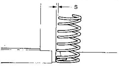
The maximum allowable value S, mm:
- Engines GA - 1.8
- Engine SR - 2.1
- CD Engines:
- External springs - 2.1 (1.8 for CD20E)
- Internal springs - 1.9 (1.6 for CD20E)
Measure the height of the springs under load (see section «Data for adjustments and control»).
If the allowable limits are exceeded, the spring must be replaced.
Valve lifters and shims (GA engines). Check the friction surfaces for visible wear, scratches and burrs.
Measure the diameters of the tappets and pilot holes in the cylinder head with a micrometer.
- Pusher diameter - 29.960-29.975 mm
- Hole diameter - 30.000-30.021 mm
- Permissible gap - 0.025-0.061 mm
If the clearance is greater than allowable, replace the tappet and/or cylinder head, depending on where the wear has exceeded the allowable limit.
Hydraulic compensators: gaps (SR engine). Check the friction surfaces for visible wear, scratches and burrs.
Measure the diameters of the hydraulic lifters and their mounting holes in the cylinder head.
- Hole diameter - 17,000-17,020 mm
- Permissible gap - 0.007 0.040 mm
Hydraulic valve lifters (cd engines). Check visual surfaces for visible wear, scratches, and nicks. Measure the diameters of the tappets and pilot holes in the cylinder head.
- Pusher diameter - 34.959-34.975 mm
- Hole diameter - 34.998-35.018 mm
- Nominal clearance - 0.023-0.059 mm
- Maximum allowable - 0.1 mm
Valve levers (SR engine). Check the friction surfaces of the levers, washers and guides for visible wear, scratches and scuffs.
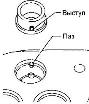
Swirl chamber replacement (cd engines). Replacing the swirl chamber is usually required quite rarely. The need for this arises in the presence of cracks or severe wear of the chamber.
1. Remove the connecting rail of the glow plugs, unscrew the spark plug and nozzle.
2. Heat the cylinder head in an oil bath to 150-160X.
3. Carefully knock out the swirl chamber, being careful not to damage the cylinder head and injector hole.
4. Install a new swirl chamber: To do this, heat the cylinder head again to 150-160X, align the chamber protrusion with the groove in the cylinder head and press the chamber with a plastic hammer.
Assembly - SA engines
1. Install valves.
Replace oil seals with every assembly (see relevant section of this chapter).
Before installing the valve stem seal, install the valve spring seat.
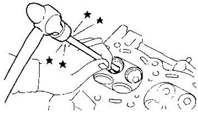
After installing the valve, hit the valve stem with a plastic mallet to ensure that the spring is secure.
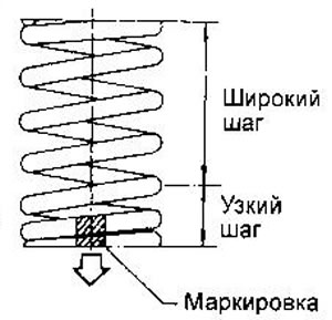
Spring coils with reduced pitch must face the cylinder head (if the spring is color coded, it should be on the bottom).
Assembly - SR Engine
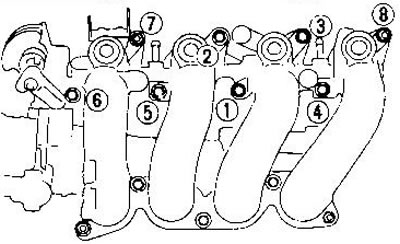
1. Attach the intake pipes to the intake manifold; following the tightening sequence of the nuts shown in the figure.
2. Install the intake manifold to the cylinder head using the nut tightening sequence shown.
3. Install the fuel rail with injectors (see chapter «Engine management system»).
4. Install the thermostat housing with water and hoses.
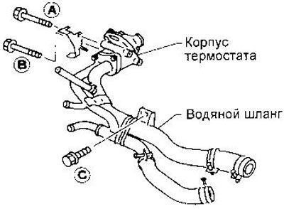
Tightening sequence:
- a) Tighten bolt A to 2-5 Nm.
- b) Tighten the bolt With a torque of 16-21 Nm.
- c) Tighten bolt A to 16-21 Nm.
- d) Tighten the bolt to a torque of 16-21 Nm.
5. Install the exhaust manifold, tightening in the sequence shown in the figure.
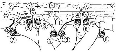
6. Establish a casing of a final collector.
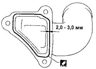
7. Install the water pipe, applying sealant to its flange. First remove all traces of old sealant from the pipe flange and cylinder head.
8. Install intake manifold brackets.
9. Install the oil separator.
10. Install valves.
The valve with the larger diameter poppet is the inlet valve.
Install only new oil seals.
Before installing the flinger cap, install the valve spring seat.
Spring coils with reduced pitch must face the cylinder head (color coding should be at the bottom).
After installing the valve, hit the valve stem with a plastic mallet to make sure the spring is secure.
11. Check the hydraulic lash adjusters.
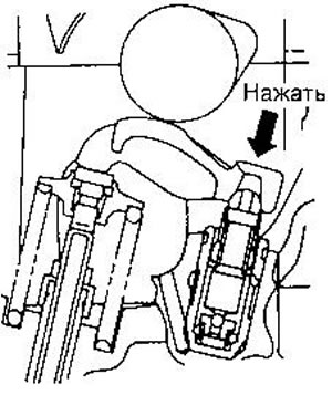
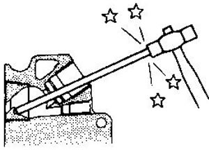
- A) Press the valve actuator lever above the hydraulic compensator. If the lever moves down at least 1 mm. there is air in the high pressure chamber. In this case, when the engine is running, specific valve noise will be heard.
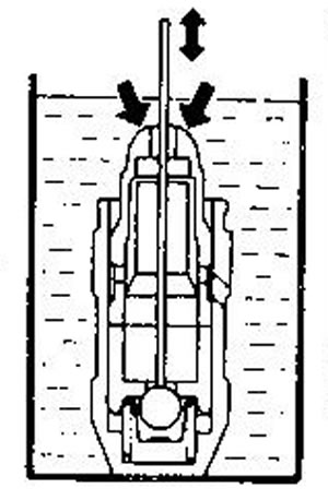
- b) To bleed air from the hydro-compensator, immerse it in a container of clean engine oil. Then, while pressing the plunger, lightly press the ball with a suitable rod. The air is completely removed when the plunger is no longer moving. It is impossible to remove air from the hydraulic compensator of this type of engine start pusher.
12. Install the valve levers, washers and lever guides.
WARNING: All parts must be installed in their original places.
13. When replacing the cylinder head, valve seat, washer or valve lever guide, adjust the shim thickness.
- a) Install all valve parts (except for the puck) into the cylinder head. The valve guide must be replaced with a new one.
- b) Remove the hydraulic clearance adjuster.
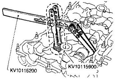
- c) Insert the KV10115700 mandrel into the hole for the hydrocompensator. A stand for a dial indicator is screwed into the mandrel.
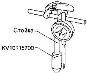
- d) Measure the height difference (T1) between the thrust surface of the lever guide and the end of the valve stem on which the washer is to be mounted. When measuring, press lightly on the indicator post to eliminate the influence of the gap in the mandrel.
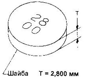
- e) Select a washer with a thickness of T = T1 = 0.025 mm. Spare parts are supplied with washers with thicknesses from 2.800 to 3.200 mm through 0.025 mm.
Assembly - CD Engines
1. Install valves.
Install only new oil seals.
Before installing the valve stem seal, install the valve spring seat.
Spring coils with reduced pitch must face the cylinder head (color coding should be at the bottom).
When installing a tapan, lubricate its stem and the edges of the oil deflector cap with engine oil.
Make sure there are no foreign particles on the valve disc.
Spring plates should be installed on the intake valves, and valve rotators should be installed on the exhaust valves.
Valve rotations are not subject to disassembly.
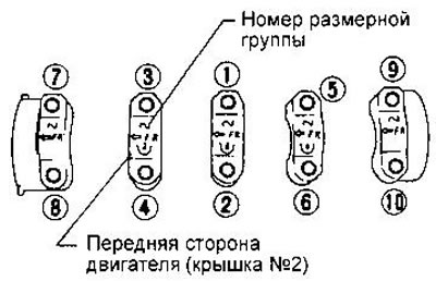
2. Install the camshaft and tighten the nuts of the bearing caps in two or three steps with a torque of 18-22 Nm.
Tightening should be done from the center to the edges, in the sequence shown in the figure.
Apply sealant to caps #1 and #5.
When installing the bearing caps, the camshaft must be installed in a position where the pin at its front end is on top.
Install new camshaft seals (see relevant section of this chapter).
Installation - CD motors
1. Apply the cylinder head gasket.
When replacing only the gasket, install the gasket of the same thickness as the previous one.
When replacing or repairing the cylinder block, pistons, connecting rods and crankshaft, select the thickness of the gasket.
Pay attention to the installation direction of the cylinder head bolt washers.
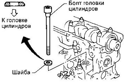
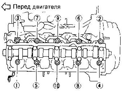
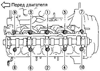
2. Install the cylinder head and tighten the bolts as follows:
- a) Tighten all bolts in the sequence shown in the figure to a torque of 39 Nm.
- b) Tighten the bolts to a torque of 83-93 Nm.
- c) Loosen all bolts completely.
- d) Tighten all bolts to 39 Nm.
- e) Tighten the bolts at an angle of 75-80°. In the absence of a wrench with a goniometer, tighten the bolts to a torque of 83-93 Nm.
3. Establish a cover of a head of cylinders, having tightened bolts in the sequence specified in drawing.
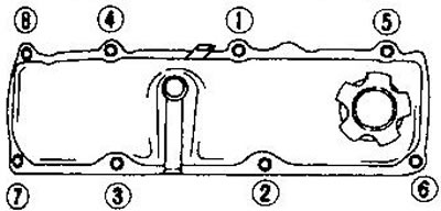
Pre-apply THREE-BOND #10 or equivalent to edges of #1 and #5 bearing caps.
Selection of the thickness of the cylinder head gasket
4. Measure the piston protrusion above the mating surface of the cylinder head.
- A) Install the dial indicator foot on the cylinder block and set the indicator to zero.
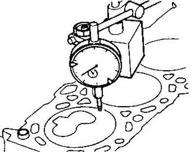
- b) Mount the indicator foot on the piston crown at the measurement point, being careful not to override the zero setting.
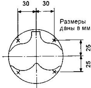
- With) Rotate the crankshaft back and forth at TDC. Record the maximum indicator reading.
- d) Install the indicator foot on the cylinder block and check that the zero setting is not disturbed.
- e) Repeat steps with) and d) days of all measuring points on the piston of each cylinder.
Make sure the piston whose protrusion is being measured. set to TDC.
2. Calculate the arithmetic mean of the measurement results for each piston.
3. Calculate the arithmetic mean of the values obtained in paragraph 2, rounding it up to the 3rd decimal place.
4. Determine the required thickness of the shim bar using the table.
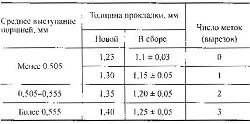
5. If the average protrusion of at least one of the pistons determined in step 2, with an increase of 0.05 mm, exceeds the upper limit for this gasket, use a gasket of the next thickness. Otherwise, use the gasket selected in step 4.