


Table of contents: General appearance ↓ Intake manifold (up to 04.96) ↓ Intake manifold (from 04.96) ↓ Removal and installation the intake…↓ Exhaust manifold ↓
General appearance
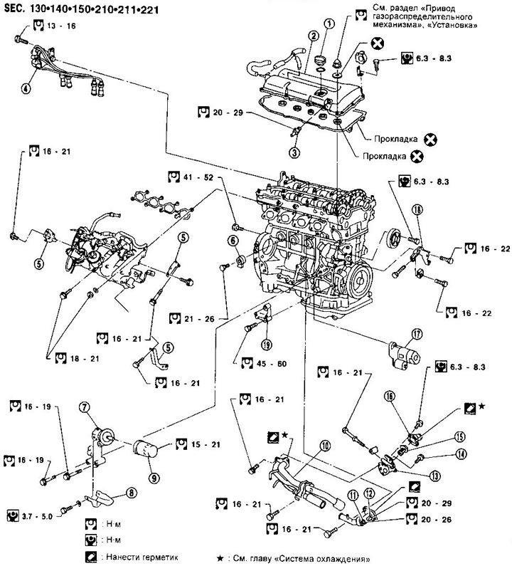
1. Filler cap
2. Cylinder head cover
3. Crankcase ventilation valve
4. Ignition distributor with camshaft angular position sensor, ignition coil and key transistor
5. Intake manifold brackets (since 04.96 the design has been changed, the tightening torques have not changed)
6. Knock sensor
7. Oil filter bracket
8. Oil catch tank
9. Oil filter
10. Water pump
11. Coolant temperature gauge sensor
12. Coolant temperature sensor
13. Thermostat housing
14. Air release valve
15. Thermostat
16. Water pipe
17. Starter
18. Power steering pump tensioner bar
19. Power steering pump bracket
Intake manifold (up to 04.96)
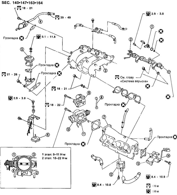
1. Nozzle
2. Fuel pressure regulator
3. Intake pipe
4. Exhaust gas recirculation pipe
5. Recirculation valve
6. EGRC-BPT valve
7. Intake manifold
8. Traction
9. Throttle control sector
10. Throttle position sensor
11. Throttle body
12. IACV regulator
13. IACV-AAC valve
14. IACV-FICD valve
Intake manifold (from 04.96)
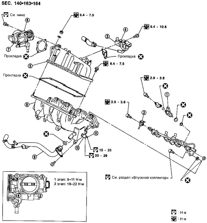
1. Nozzle
2. Fuel pressure regulator
3. IACV-AAC valve
4. IACV-FICD valve
5. Intake manifold
6. Throttle body
7. Throttle position sensor
8. Intake pipe
9. Water pump
10. Coolant temperature sensor
11. Coolant temperature gauge sensor
Removal and installation the intake manifold (sr20de engine since 04.96)
Removal
1. Release the pressure in the fuel system (see chapter "Fuel injection system").
2. Remove the lower engine splash guard, right front wheel and side splash guard.
3. Drain the coolant.
4. Remove the cross member connecting the shock absorber strut supports.
5. Disconnect the air duct from the intake manifold.
6. Disconnect the crankcase ventilation hoses from the cylinder head cover.
7. Disconnect vacuum hoses, fuel lines, water hoses, wires, etc. from the intake manifold.
8. Remove the drive belts and water pump pulley.
9. Remove the power steering pump and its bracket.
10. Remove the power steering pump tensioner bar.
11. Remove the oil filter bracket.
12. Remove the intake manifold support brackets.
(The source of the article is on the website: «nissanbook.ru»)
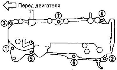
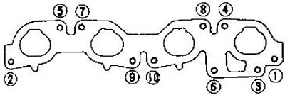
13. Disconnect the intake manifold from the intake pipes by loosening the nuts in the sequence shown in the figure.
14. Disconnect the connectors from the coolant temperature sensor and the temperature gauge sensor.
15. Remove the fuel rail.
16. Remove the intake pipe brackets.
17. Remove the intake pipes by loosening the nuts in the sequence shown in the figure.
Installation
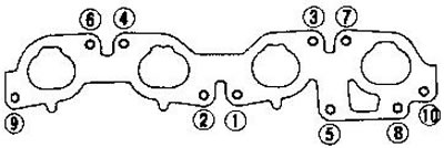
1. Install the intake pipes by tightening the nuts in the sequence shown in the figure.
2. Install the intake pipe brackets.
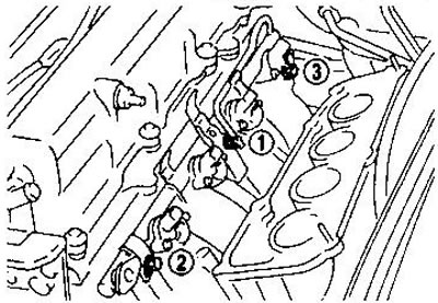
3. Install the fuel rail. Tighten the bolts in two stages: first with a torque of 9.3-10.8 Nm, then with a torque of 21-26 Nm. The tightening sequence is shown in the figure.
4. Connect the temperature sensor and temperature gauge sensor connectors.
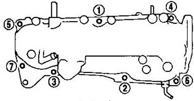
5. Install the intake manifold and support brackets. Tighten the bolts in the sequence shown in the illustration.
Exhaust manifold
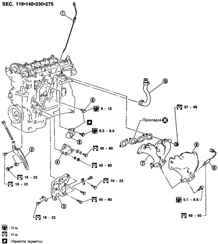
1. Oil dipstick
2. Generator tension bar
3. Compressor bracket
4. Generator bracket
5. Water pipe
6. Drain plug
7. Exhaust manifold
8. Oxygen sensor
9. Exhaust manifold casing
10. Crankcase ventilation hose