Table of contents: Disassembly ↓ Examination ↓ Cylinder boring ↓ Replacing the upper connecting rod…↓ Assembly ↓
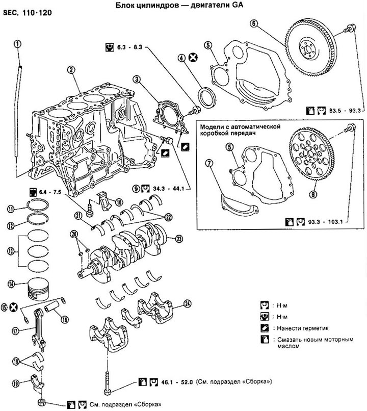
1. Oil dipstick tube
2. Cylinder block
3. Crankshaft rear oil seal holder
4. Rear oil seal
5. Back cover
6. Flywheel
7. Bottom cover
8. Leading disk
9. Cooling jacket drain plug
10. Buffer plate
11. Upper compression ring
12. Lower compression ring (only for Europe GA14DE and GA16DE engines without VTC)
13. Oil scraper ring
14. Piston
15. Retaining rings
16. Piston pin
17. Connecting rod
18. Connecting rod bearing shells
19. Connecting rod bearing cap
20. Keys
21. Main bearing shell
22. Thrust half rings
23. Crankshaft
24. Main bearing cap
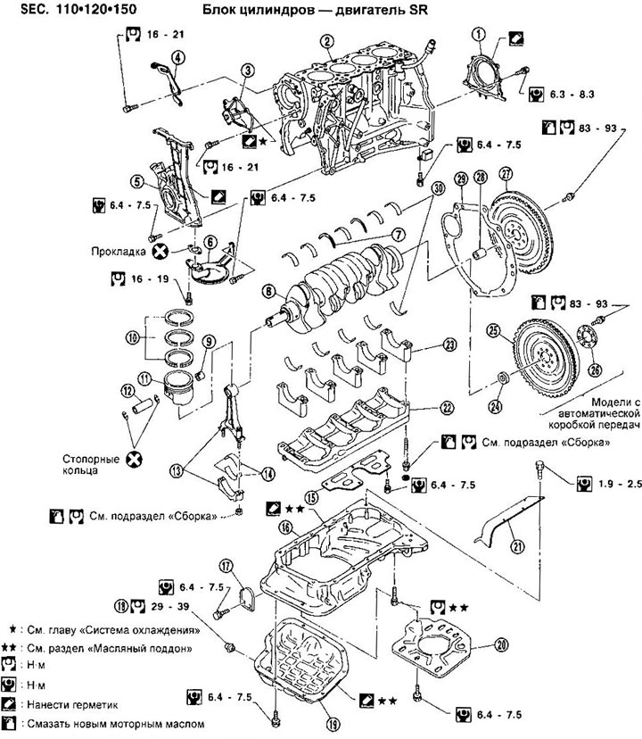
1. Crankshaft rear oil seal holder
2. Cylinder block
3. Water pump
4. Power steering pump tensioner bar
5. Front crankcase with oil pump
6. Oil receiver
7. Thrust half ring
8. Crankshaft
9. Connecting rod bushing
10. Piston rings
11. Piston
12. Piston pin
13. Connecting rod
14. Connecting rod bearing shells
15. Partition*
16. Aluminum tray
17. Back cover
18. Drain plug
19. Steel pallet
20. Partition
21. Lateral partition*
22. Main bearing side member*
23. Main bearing cap
24. Guide bushing
25. Leading disk
26. Reinforcement ring
27. Flywheel
28. Guide bushing
29. Back cover
30. Main bearing shells
*Not available in SR20DE engines for Europe since 04.96
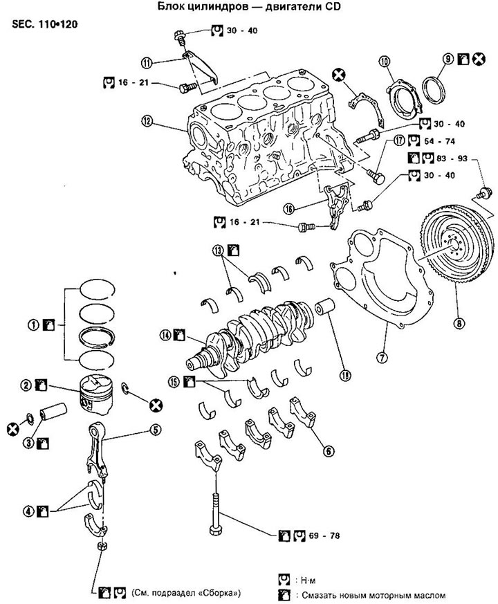
1. Piston rings
2. Piston
3. Piston pin
4. Connecting rod bearing shells
5. Connecting rod
6. Main bearing cap
7. Back cover
8. Flywheel
9. Rear crankshaft oil seal
10. Rear oil seal holder
11. Support bracket
12. Cylinder block
13. Main bearing shells
14. Crankshaft
15. Main bearing shells
16. Support bracket
17. Cooling jacket drain plug
18. Guide bushing
Disassembly
Crankshaft and connecting rod and piston group.
1. Place the engine on the disassembly stand.
2. Drain the coolant and oil.
3. Remove the drive chain or timing belt (see section "Timing drive").
4. For CD engines, remove the water and oil pumps.
5. Remove the cylinder head (see section "Timing drive" for GA and SR engines or "Cylinder head" for CD engines).
6. Remove the oil pan (see section "Oil pan").
7. Remove the pistons with connecting rods. Remove the piston pin retaining rings. To press the piston pins, heat the pistons to 60-70°C or use a press stand at room temperature.
8. Remove the crankshaft rear oil seal holder.
9. Loosen the main bearing cap bolts in the sequence shown in the figure, then remove the crankshaft.
Before removing the main bearing caps, measure the axial free play of the crankshaft.
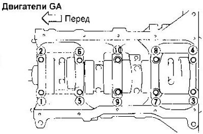
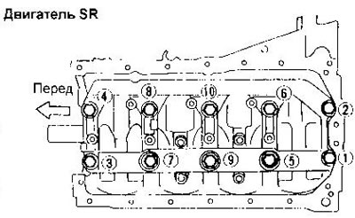
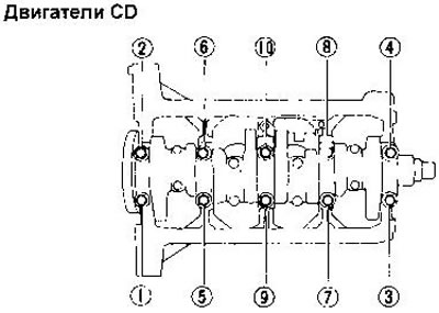
The cap bolts should be loosened in two or three steps.
The main bearing shells and caps must be installed in their original places during assembly, so be careful not to mix them up after removal.
10. Remove the piston rings using a suitable puller.
Examination
Piston to piston pin clearance. Measure the inside diameter of the piston bore and the outside diameter of the piston pin.
Nominal piston bore diameter, mm:
- GA engines - 18.987-18.999
- Engine SR - 21,987-21,999
- CD engines - 24.991-24.999
Nominal piston pin diameter, mm:
- GA engines - 18,989-19,001
- Engine SR - 21,989-22,001
- CD engines - 24,994-25,000
Calculate the clearance by subtracting the piston pin diameter from the bore diameter. The result should be between -0.004 mm and 0 mm. If the clearance is positive, replace the piston with the piston pin. The height clearance between the piston rings and the grooves. Measure the specified clearance with a feeler gauge. To obtain the correct result, the feeler gauge must enter the groove as far as it will go.
The maximum permissible clearance is 0.2 mm for all rings on GA and SR engines, and 0.1 mm for all rings on CD engines.
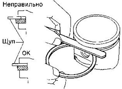

If the clearance is not within the specified limits, replace the piston and/or piston rings.
Clearances in piston ring locks. Press the piston ring into the cylinder as shown in the figure and measure the gap with a feeler gauge.
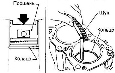
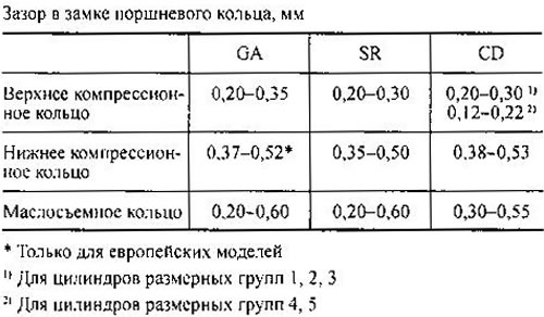
The maximum permissible gap in the locks of all piston rings of GA and SR engines is 1.0 mm.
In CD engines, the maximum permissible clearances are as follows:
- Upper compression ring - 1.0 mm
- Lower compression ring - 0.7 mm
- Oil scraper ring - 0.6 mm
If the clearance is not within the specified limits, replace the piston ring. If the clearance does not return to normal after this, bore the cylinder and install a piston with repair-size rings (see section "Data for adjustments and control").
If the piston needs to be replaced, also check the condition of the cylinder. If there are scratches or scoring on the cylinder walls, hone the cylinder or replace the cylinder block.
Bending and twisting of connecting rods. The maximum permissible values of bending and torsion per 100 mm of length are as follows:
- GA and SR motors: bending - 0.15 mm, torsion - 0.30 mm.
- CD motors: bending and torsion - 0.025 mm.
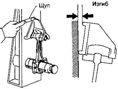
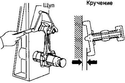
Deformation of the cylinder block. Clean the mating surface of the cylinder block and measure its flatness by applying a metal ruler in six directions.
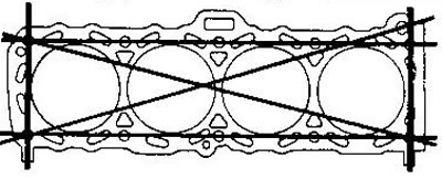
The maximum permissible deviation from flatness is 0.1 mm for all engines. If this value is exceeded, regrind the mating surface or replace the cylinder block.
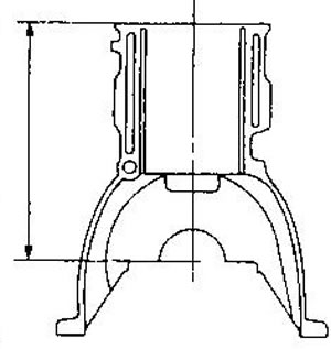
The permissible reduction in the height of the cylinder block after processing is determined from the condition A + B = 0.2 mm (0.1mm for CD engine), where A is the reduction in the height of the cylinder head after processing; B - reduction of the cylinder block height.
Nominal height of cylinder block (from the crankshaft axis), mm:
- GA: 213,95-214,05
- SR: 211,25-211,35
- CD: 211,25-211,35
Piston to cylinder clearance. Using a bore gauge, measure the cylinder's internal diameter, ovality, and taper.
Measurements are taken at a depth of 20, 60 and 100 mm for GA engines; 10, 60 and 100 mm for SR engine; 20, 70 and 120 mm for CD engines.
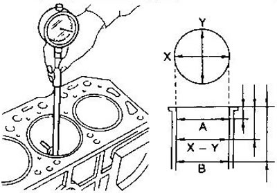
- Nominal cylinder diameter, mm:
- Engines GA14DE, 15DE - 73,600-73,630
- Engine GA16DE - 76,000-76,030
- SR Engine - 86,000-86,030
- CD engines - 84,500-84,550
- Permissible ovality (XY) - no more than 0.015 mm
- Permissible taper (A-B) - no more than 0.010 mm
The maximum permissible wear is 0.2 mm for the cylinders of all engines.
If the wear of at least one cylinder exceeds 0.2 mm, bore all cylinders. If necessary, replace the cylinder block.
If there are scratches or burrs on the cylinder surface, hone the cylinder.
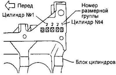
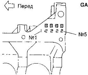
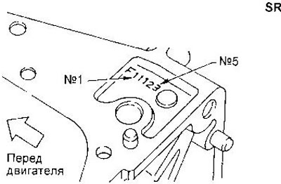
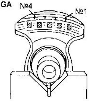
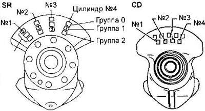
When replacing the cylinder block and pistons at the same time, the black groups of the pistons must match the black groups of the cylinders indicated on the cylinder block.
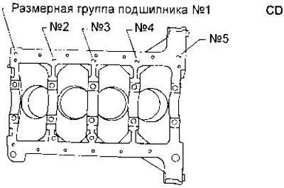
For SR and CD engines, the group numbers are marked on the mating surface next to the holes of the corresponding cylinders, and for GA engines - in the place shown in the figure.
Measure the diameter of the piston skirt perpendicular to the piston pin. The distance (a) from the edge of the skirt to the plane of measurement, as well as the diameter values, are given in the section "Data for adjustments and control".
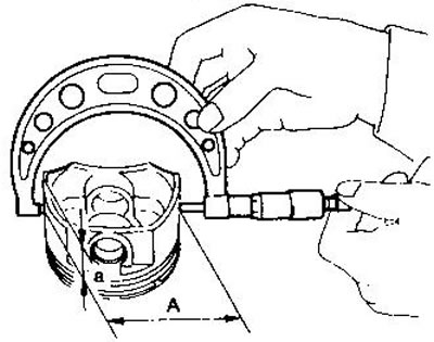
Permissible clearance between piston and cylinder, mm:
- GA engines - 0.015-0.035 mm
- SR Engine - 0.010-0.030 mm
- CD motors - 0.025-0.045 mm
If the clearance exceeds the specified value, select pistons of a repair size and bore the cylinders (see subsection "Cylinder boring").
Crankshaft. Check the condition of the main and connecting rod journals. They should not have any scoring, signs of wear or cracks.
Use a micrometer to determine the taper and ovality of the journals.
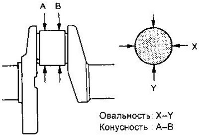
Ovality (XY) and taper (A-B), mm:
- Engines C A - no more than 0.005 (taper no more than 0.002)
- SR Engine:
- Main necks - no more than 0.005
- Connecting rod journals - no more than 0.0025
- CD engines - no more than 0.005
Measure the crankshaft runout by mounting the shaft on prisms. The runout value is the difference in the indicator readings for one complete revolution of the shaft.
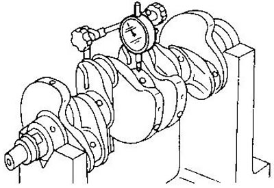
- Radial runout - no more than 0.005 mm
Clearances in main and connecting rod bearings. There are two ways to measure gaps: using a micrometer and bore gauge, or using a plastic wire. The first method is preferable, as it gives more accurate results.
Main bearings: Install the bearing shells into their places in the cylinder block.
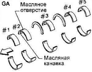
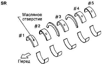
Install the bearing caps and tighten the bolts to the required torque in two or three steps. Observe the tightening sequence.
Measure the inner diameters of the main bearings and the outer diameters of the crankshaft main journals.
Nominal clearance in main bearings, mm:
- GA engines - 0.018-0.042
- SR Engine - 0.004-0.022
- CD engines - 0.039-0.065
The maximum permissible clearance is 0.1 mm for GA engines and 0.050 mm for SR engines. For CD engines, the clearance must be within the above limits.
If the gap exceeds the specified values, replace the bearings.
If the gap cannot be normalized by replacing the liners, or the journals have any damage (scratches, nicks), they must be ground to the nearest repair size and thicker liners must be installed (see section "Data for adjustments and control").
The transitions between the crankpins and cheeks must be machined in a specific way (see pictures).
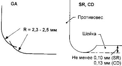
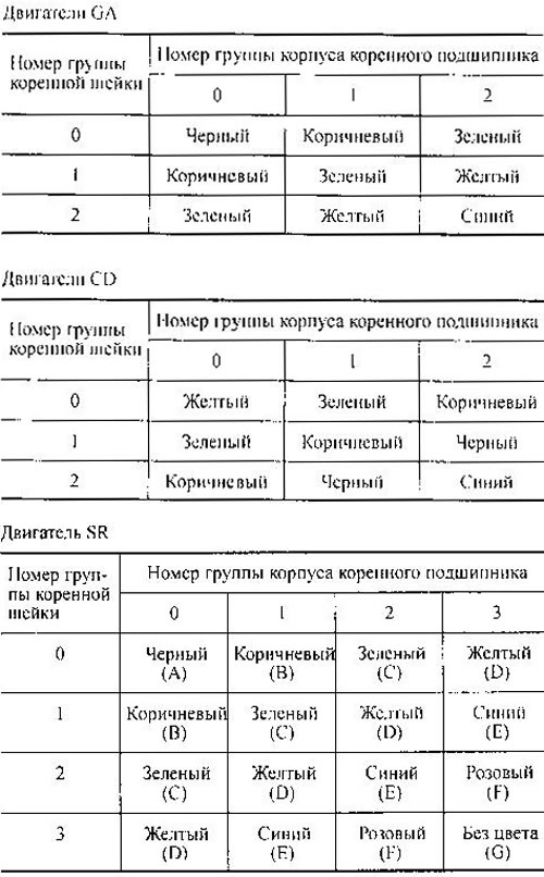
If the crankshaft, cylinder block or bearing shells are to be reused, measure the clearance in the main bearings. When replacing all of the listed parts, the thickness of the liners is selected as follows:
a) The numbers of the dimensional groups of the main bearing housings are stamped on the cylinder block in Arabic or Roman numerals.
b) The numbers of the size groups of the crankshaft main journals are stamped on the crankshaft counterweight in Arabic or Roman numerals.
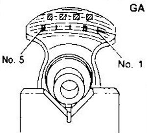
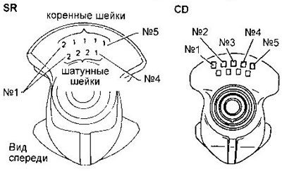
On SR engines, the front crankshaft counterweight may have group numbers stamped on it for the main and connecting rod journals (as shown in the picture) or just the numbers of the molar neck groups.
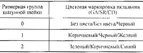
c) The thickness of the liners is determined according to the tables. The color marking is applied to the end surface of the liners.
Connecting rod bearings (lower connecting rod head). Insert the liners into the connecting rod and connecting rod bearing cap. Install the cap and tighten the bolts to the specified torque.
Measure the inside diameter of each connecting rod bearing. Then measure the diameter of the crankshaft journals.
Nominal clearance in connecting rod bearings, mm:
- GA engines - 0.014-0.039
- SR Engine - 0.020-0.045
- CD engines - 0.031-0.055
The maximum permissible clearance is 0.1 mm for GA engines and 0.065 mm for SR engines. For CD engines, the clearance must be within the above limits.
If the gap exceeds the specified values, replace the bearings.
If the gap cannot be normalized by replacing the liners, or the journals have any damage (scratches, nicks), they must be ground to the nearest repair size and larger diameter liners must be installed (see section "Data for adjustments and control").
When grinding connecting rod journals, take into account the requirements for processing the transitions between the journals and crank cheeks, similar to the main journals.
If the crankshaft, connecting rods or bearing shells are replaced, select the bearing shell thickness according to the tables.
The crankpin size groups are stamped on the crankshaft counterweight. For SR engines they may be stamped on the rear counterweight (see picture) or on the front along with the numbers of the main journal groups.
Clearance between the connecting rod upper head bushing and the piston pin. Measure the inner diameter of the bushing and the outer diameter of the piston pin. Nominal clearance, mm:
- GA and SR engines - 0.005-0.017
- CD engines - 0.025-0.044
The maximum permissible clearance for GA and SR engines is 0.023 mm. For CD engines, the clearance must be within the limits specified above.
If the clearance exceeds the specified values, replace the connecting rod, connecting rod bushing and/or piston with piston pin.
Flywheel/drive disk axial runout. Measure the flywheel runout using a dial indicator. The runout value is the difference in the indicator readings for one complete revolution of the flywheel.
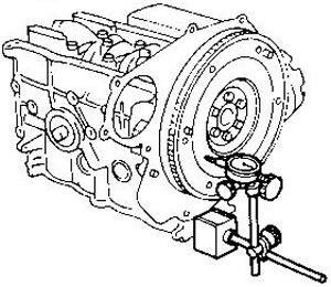
Axial runout, mm:
- GA and SR engines (flywheel) - no more than 0.15
- GA and SR engines (leading disk) — no more than 0.2*
- CD engines (flywheel) - no more than 0.15
* At a distance of approximately 115 mm from the crankshaft axis.
Cylinder boring
1. Based on the measured clearance between the piston and the cylinder, determine the required piston repair size (see section "Data for adjustments and control").
2. Calculate the cylinder diameter using the formula:
D = A - B + C, where:
D — cylinder diameter after boring,
A is the piston diameter,
B is the required clearance between the piston and the cylinder.
C — honing allowance (0.02 mm).
3. Install the main bearing caps and tighten the bolts to the specified torque. This will prevent deformation of the cylinder bores.
4. Bore the cylinders.
If even one cylinder requires boring, all cylinders must be bored.
Perform boring in several passes, increasing the diameter each time by approximately 0.05 mm.
5. Hone the cylinders to obtain the required clearance between the piston and cylinder.
6. Measure the ovality and taper of the cylinder. Measurements must be taken after the cylinder block has completely cooled down.
Replacing the upper connecting rod head bushing
1. You press the old bushing using a suitable mandrel.
2. Press the new bushing flush with the connecting rod head surface. Make sure the oil holes are aligned.
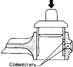
3. Turn the bushing to provide a clearance with the piston pin of 0.005-0.017 mm in GA and SR engines. In CD engines, the bore diameter should be 25.025-25.038 mm (gap 0.025-0.044 mm).
Assembly
1. Install a new snap ring into one of the piston holes.
2. Heat the piston to 60-70°C and connect it to the connecting rod. Install the second retaining ring (also new).
Observe the relative orientation of the piston and connecting rod.
The number of the corresponding cylinder is stamped on the connecting rod and the connecting rod bearing cap.
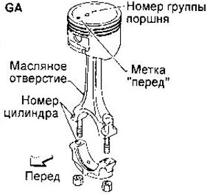
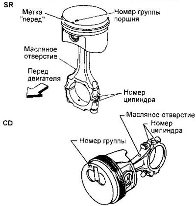
After assembly, make sure that the connecting rod turns smoothly, without jamming.
3. Put on the piston rings as shown in the picture. If there is a mark on the ring, it should be facing up.
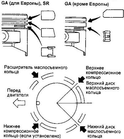
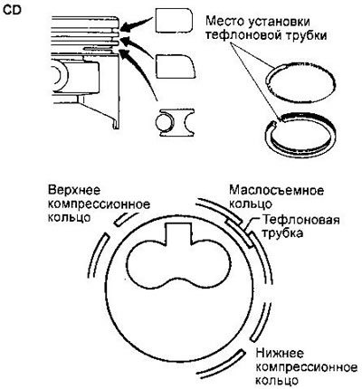
If piston rings are not replaced, they must be installed in their previous position. Installation of new piston rings without a stamped mark is allowed on either side.
When replacing the upper compression ring or cylinder block in CD engines, it is necessary to select a ring with the required clearance in the lock. For cylinders of size groups 1, 2 and 3, rings without a mark are intended, and for cylinders of groups 4 and 5, rings with the S mark are intended.
4. Install the main bearing shells and lubricate them with new engine oil, Upper shells (in the cylinder block) have oil grooves and/or holes. The upper shells of the 3rd main bearing in GA and SR engines are installed with thrust half rings. In CD engines, flanged shells are used instead of half rings.
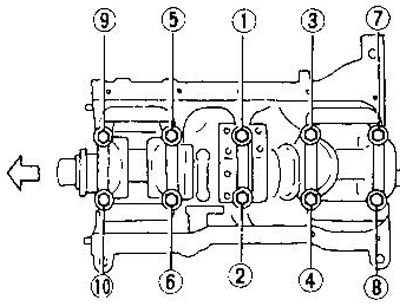
5. Install the crankshaft and main bearing caps. The bearing numbers are marked on the caps.
Apply new engine oil to the threads and seating surfaces of the main bearing bolts. Before tightening the bolts, set the main bearing caps in their normal position by sliding the crankshaft back and forth in the axial direction. On GA and CD engines, tighten the cap bolts in two or three steps, in the sequence shown in the figure.
For SR engines the tightening procedure is as follows:
- a) Tighten all bolts to a torque of 26-32 Nm (in SR20DE engines for Europe since 04.96 - 7-13 Nm) in the sequence shown in the figure (shown is a cylinder block for European model engines from 04.96).
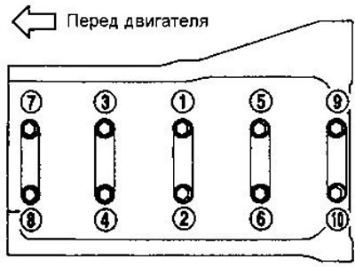
- b) Tighten all bolts by 75-80°.
- c) Loosen all bolts completely.
- d) Retighten all bolts to 32-38 Nm.
- e) Tighten all bolts by 45-50° (30-35° in SR20DE engines for Europe from 04.96). If you do not have a spanner with a protractor, you can use a protractor to measure the angles. It is not recommended to do this operation by eye.
After finishing tightening, make sure that the crankshaft rotates smoothly by hand.
6. Measure the axial free play of the crankshaft using a dial indicator (along the end of the shaft) or feeler gauge (in the central bearing).
Nominal free travel, mm:
- GA engines - 0.060-0.180
- Engine SR - 0.10-0.26
- CD engines - 0.05-0.18
The maximum permissible free play for all motors is 0.30 mm.
7. Install the connecting rod bearing shells in their places.
The oil holes in the connecting rod bearing and connecting rod must match.
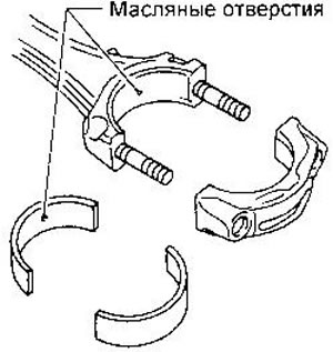
Apply new engine oil to the threads and bolt seating surfaces.
8. Insert the pistons with connecting rods into the appropriate cylinders using a piston ring compressor. The marks on the piston crowns should face the front of the engine. Be careful not to scratch the cylinder walls with the connecting rods.
Lubricate the piston rings and piston friction surfaces with engine oil.
9. Install the connecting rod bearing caps. The connecting rod bearing caps and connecting rods must have the same markings (cylinder number). Tighten the connecting rod bearing nuts, setting the pistons one by one to BDC.
a) Tighten the nuts to the following torque
- GA engines - 13.8-15.7 Nm
- SR engines - 14-16 Nm
- CD engines - 15 Nm
b) Tighten the nuts to the specified angle or tighten them to the specified torque:
- GA engines - 35 40° (23-28 Nm)
- SR Engine - 60-65° (38-44 Nm)
- CD engines - 60-65° (37-45 Nm)
10. Measure the axial clearance in the connecting rod bearings using a feeler gauge.
Nominal axial clearance:
- GA engines - 0.20-0.47 mm
- SR Engine - 0.20-0.35 mm
- CD engines - no more than 0.30 mm
The maximum permissible clearance is 0.50 mm for GA and SR engines and 0.30 mm for CD engines.
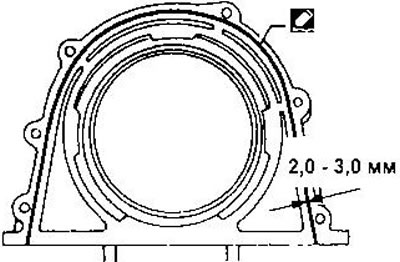
11. Install the rear oil seal retainer. First remove all traces of old sealant from the retainer and cylinder block mounting surfaces and apply a continuous bead of sealant, going around the inside of the bolt holes.