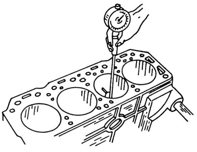
Measuring a cylinder with an internal micrometer.
If there is no indicator, the following operations cannot be performed. Cylinder measurements should be made in the longitudinal and transverse directions (illustration below). You should also consider the differences between injection and carbureted engines.
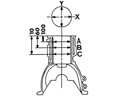
Cylinder Block Measurement Chart. Take measurements at levels A, B and C and in directions "X-X" And "Y-Y".
1. On an injection engine, the measurement should be made according to the illustration above, i.e. 10 mm, 60 mm and 100 mm from the top edge. Take measurements in directions "X" And "Y".
2. On a carbureted engine, the first measurement is made 20 mm from the top edge of the cylinder, the rest as in the previous paragraph.
3. A total of 6 measurements are required per cylinder. Record all values and compare with the values in Specifications at the beginning of the chapter. Thanks to precise measurements, ovality is determined (size difference "A" And "IN") and taper (difference between upper and lower measurement values). It should be remembered that all cylinders must be bored, even if only one cylinder is out of tolerance. Deviation from the required dimensions by 0.04 mm is acceptable. Repair sizes of pistons are available in Specifications at the beginning of the chapter. The final diameter of the cylinder is determined by measuring the piston according to the illustration below, i.e. the micrometer grips are set to 9.5 mm (carbureted engine) or 11.0 mm (injection engine) from the lower edge of the piston at an angle of 90°to the piston pin. Add a clearance value of 0.010 - 0.030 mm to this dimension (injection engine) or 0.015 - 0.035 mm (carbureted engine). In addition, the addition of 0.02 mm for the final grinding of the cylinders should be taken into account. To check the piston clearance, measure the piston and cylinder as described and calculate the difference between the dimensions for each cylinder.
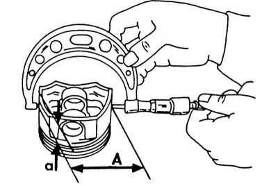
Piston diameter measurement. Size "A" for injection and carburetor engines is not the same.
4. If there is no experience in measuring, the block should be taken to a special workshop and measured there.
For clarity, you can draw a sketch and record the measurement results there. The difference between the top and bottom measurements reflects the taper. The difference between transverse and longitudinal measurements reflects ovality. Nowhere should the diameter differ from the required value by more than 0.04 mm.
5. Numbers are stamped on the top surface of the cylinder block to indicate the size class of the pistons. When replacing a cylinder block, pistons of the appropriate size class must be installed. Check the surface of the cylinder block for deformation as shown in the illustration below.
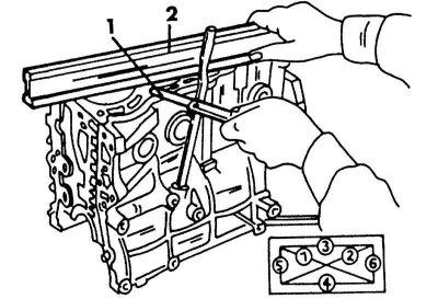
Measuring deformation of the surface of the cylinder block
1 - probe
2 - steel ruler
6. To do this, place a steel ruler on the surface of the block (2) and measure the clearance with a feeler gauge (1). Measure the block in the longitudinal, transverse and diagonal directions as shown in the small diagram. The maximum allowable size is 0.10 mm. It should be remembered that the head and cylinder block can be ground by a total of no more than 0.2 mm. If the head does not need to be ground, check the height of the cylinder head, the size is indicated in Specifications at the beginning of the chapter. If the cylinder block after grinding is less than the permissible height, it must be replaced.