


Table of contents: Removal and installation the pump ↓ Oil pump overhaul ↓
Removal and installation the pump
1. Removal and installation of the oil pump on an injection and carburetor engine is carried out in the same way.
2. Remove all drive belts from the end of the engine.
3. Remove the cylinder head (Section Cylinder head and timing drive).
4. Remove the oil pan (Chapter Cooling and heating systems).
5. Remove the oil suction screen and oil passage plate.
6. Remove the camshaft drive cover (Section Cylinder head and timing drive).
7. Disassemble the pump as described in the next chapter.
8. Before installing the camshaft drive cover, remove all remaining sealant with a scraper. Also clean the surface of the cylinder head. Coat the cover surface with sealant and install all parts in the reverse order.
Oil pump overhaul
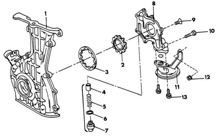
Oil pump parts for injection engine
1 - timing gear drive cover; 2 - internal pump gear; 3 - external pump gear; 4 - piston of the pressure reducing valve; 5 - pressure spring; 6 - sealing washer; 7 - cork; 8 - oil pump cover; 9 - bolt, 4-5 Nm; 10 - bolt, 6.5-8.5 Nm; 11 - oil suction mesh; 12 - nut, 6.5-7.5 Nm; 13 - bolts, 13-16 Nm
The illustration above shows the oil pump of an injection engine. The same parts are used on a carburetor engine, only the gears have a different design.
1. Unscrew the cap from the inside of the camshaft drive cover, wipe both gears and use a small screwdriver to make a mark on the outside of both gears. On a carburetor engine, the inner gear has a groove on the outer circumference, which should face the pump cover after assembling the pump.
2. Remove both gears from the pump bore.
3. Remove the pressure reducing valve after removing the plug with the spring.
4. Insert both gears back into the housing and measure the clearance between the top side of the pump housing and the top side of the gears by applying a steel ruler and measuring with a flat feeler gauge as shown in the illustration. The maximum allowable clearance is 0.10 mm between the ruler and the inner gear and 0.11 mm between the ruler and the outer gear. If necessary, the clearance can be reduced slightly by removing a little surface of the pump housing with sandpaper.
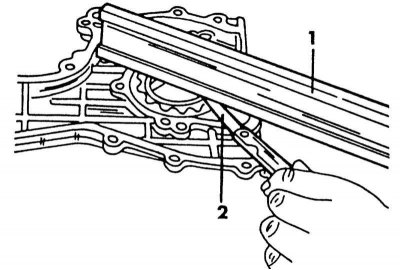
Measuring the axial clearance of the pump gears using a steel ruler (1) and a feeler gauge (2).
5. Insert a narrow feeler gauge between the outside of the outer gear and the housing hole. The gap should not exceed 0.20 mm. The illustration below shows the measurement. Also, as shown in the illustration, measure the gap between the teeth lying together. The gap should be less than 0.18 mm.
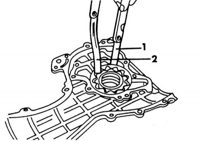
Measuring the clearances between the external pump gear and the bore (1), as well as between the teeth of the pump gear (2).
6. The carburetor engine pump has a sickle-shaped insert inserted into the housing. Measure the gaps between the insert and the teeth of the corresponding gear for such a pump and compare them with the data given in Specifications.
7. If the measured values exceed the wear limit, either the pump gears or the camshaft drive cover must be replaced. The oil pump is assembled in the reverse order. Insert the gears according to the markings. For the internal pump gear on a carburetor engine, the side of the gear with the outer groove must be visible before installing the pump cover. Before installation, lubricate the pump gears well to prevent the pump from seizing when the engine is first started. If the pressure relief valve parts have been replaced, check the condition of the valve piston hole. Screw in the plug with a new gasket and tighten to 50 - 70 N·m (for injection engine) or 40 - 60 Nm (for carburetor engine).