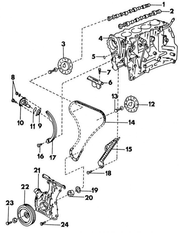
Elements of the drive of the distribution mechanism of the injection engine
1 - right camshaft; 2 - left camshaft; 3 - camshaft sprocket; 4 - cylinder block; 5 - round seal; 6 - upper chain guide; 7 - bolt, 16-19 Nm; 8 - bolt, nut, 6-8 Nm; 9 - gasket; 10 - chain tensioner; 11 - round seal; 12 - camshaft sprocket; 13 - bolt, 137-157 Nm; 14 - drive chain; 15 - chain guide; 16 - bolt, 13-19 Nm; 17 - chain guide; 18 - bolt, 13-19 Nm; 19 - crankshaft sprocket; 20 - remote element; 21 - cover of the timing mechanism drive; 22 - belt pulley; 23 - bolt, 145-155 Nm; 24 - bolt, 6.5-7.5 N·m
1. Reduce the pressure in the power supply system, as described in Section Removal and installation of the engine. To do this, remove the illustrations fuse.
2. Unscrew all panels under the front of the car.
3. Place the front of the car on supports, unscrew the right wheel and unscrew the shield in the front right wheel arch.
4. Drain the coolant as described in Chapter Cooling and heating systems.
5. Remove the radiator.
6. Remove the suction air hose to the intake manifold.
7. Loosen and remove the drive belt on the front side of the engine. Unscrew the water pump pulley.
8. Remove the generator.
9. Remove the power steering pump.
10. Remove the throttle cable.
11. Remove all spark plugs.
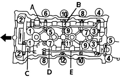
12. Remove the cylinder head cover. In order not to overtighten the cover, a certain sequence must be observed when loosening the bolts. It is shown in the illustration below. On the side of the cylinder head there is an oil deflector, which must be removed.
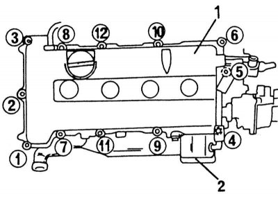
Cylinder head cover bolt loosening sequence. Tighten in reverse order
1 - cylinder head cover
2 - oil deflector
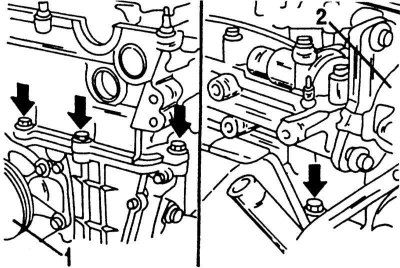
13. Unscrew all supports of the inlet pipeline. The SR20DE engine uses several mounts, which are shown in illustrations. The SR20Di engine uses only one support.
14. Remove the oil filter cartridge and power steering pump console.
15. Turn the crankshaft (by installing the socket on the crankshaft belt pulley bolt), until the mark on the belt pulley is opposite the pointer on the timing cover (see illustration below). In this position, the control marks of each camshaft drive gear are in the position shown in the illustration.

Control Labels (1) on the camshaft sprockets must be in the indicated position when the piston of the 1st cylinder is in the TDC position
1 - control labels
2 - right asterisk
3 - left sprocket
16. Remove the nut and bolt and remove the chain tensioner from the cylinder head. The tensioner has a gasket and an O-ring seal. Both parts should be replaced.
17. Remove the distributor cap and inspect the distributor head. The distributor slider will be in the position shown in the illustration. To remember this position, you should draw a line on the distributor body with a scriber opposite the middle of the slider. Then remove both bolts (arrows) and remove the distributor.
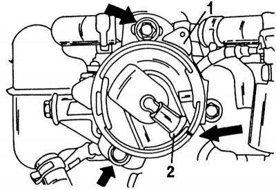
Before removing the distributor (2) hold on the hull (arrow) line opposite the slider (2).
18. Loosen the two bolts and remove the chain guide.
19. Loosen both camshaft sprocket bolts. In this case, the shafts should be kept from turning. Behind the sprocket, the shaft has a hexagon on which you can install an adjustable wrench, as shown in the illustration below.
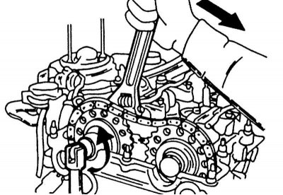
Loosening the camshaft sprocket bolts.
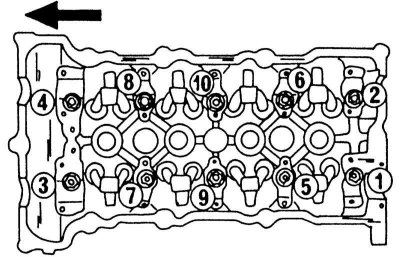
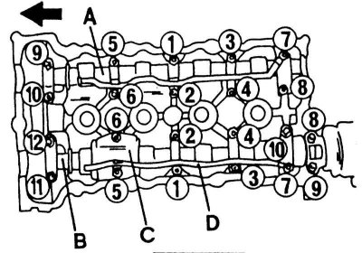
20. Remove the camshaft bearing caps, camshafts, oil line and conductive plate. When loosening the bearing caps, a certain sequence must be followed. It is shown in the illustration below.
Camshaft bearing cap bolt loosening sequence
A - right camshaft; B - camshaft bearing caps; C - left camshaft; D - conductive plate; E - oil pipeline
21. After loosening the hose clamps, disconnect the following hoses: the hose to the cylinder block, the hoses from the heater and, if available, the water hose from the oil cooler.
22. On the SR20DE engine, remove the starter. Also on this engine, unscrew the water pipe.
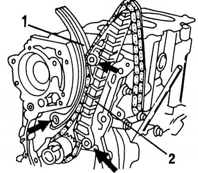
23. Unscrew bolts of a head of cylinders on outside. They are in the locations shown in the illustration below, three next to the water pump pulley and one next to the ignition distributor.
The position of the outer cylinder head bolts. Three on the side of the water pump pulley (1) and one on the distributor side (2).
24. Loosen the cylinder head bolts from the outside to the middle in even passes and lift the cylinder head. The intake manifold and exhaust manifold remain on the head. The illustration below shows the bolt loosening sequence. If the head is stuck to the block, you can tap it with a rubber mallet. Never try to insert a screwdriver between the sealing surfaces. Place the head on a workbench if it is to be disassembled or repaired.
Cylinder head bolt loosening sequence. The arrow points forward.
25. Remove the oil pan (Chapter Cooling and heating systems).
26. From the underside of the crankcase, remove the oil suction screen and oil guide plate.
27. Loosen the crankshaft pulley bolt. To fix the shaft from turning, you can turn on the gear. Press out the belt pulley with two pry bars. The firmly seated camshaft can be removed with a puller. To install the puller shown in the illustration below, there are two threaded holes in the belt pulley.
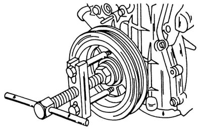
Removing the crankshaft pulley.
28. Now the engine should be lifted from the supports. To do this, you can use a mobile lift with a suitable steel plate so that the plate rests against the frame of the crankshaft main bearings.
29. Remove the front engine mount.
30. Unscrew the timing gear cover at the end of the engine. A total of 9 bolts must be loosened.
31. Loosen the bolts shown in the illustration below and remove the right (1) and left (2) guide chains.
Installation of the right (1) and left (2) chain guides.
32. Remove the drive chain, if required, remove the crankshaft sprocket. Remember how she is dressed. Thoroughly clean and check all parts, especially the timing gear parts. Worn sprockets are identified by very shiny spots, which can also be seen on the chain rollers. Checking the parts of the cylinder head, including the camshafts, is discussed next. When installing parts of the timing gear drive and cylinder head, proceed in the following sequence. All necessary tightening torques are indicated on illustrations, they are also indicated in the text.
33. Drive the sprocket onto the crankshaft. The shoulder of the sprocket must face the crankshaft. Make sure the key is inserted correctly.
34. Turn the crankshaft so that the key in the sprocket is vertically up. The control mark on the sprocket is in position «for 4 hours». Examine the chain and find the marked link. On one side of the chain, two marks can be found, spaced 20 links apart. They serve for camshafts. If you count 48 links, you can find a mark for the crankshaft. This link also has a different color from the other two. Place the chain on the crankshaft sprocket so that the marks match.
35. According to illustrations Install and tighten guide chains. Hang the chain at the top in a loose state.
36. Remove the old gasket from the timing cover and from the sealing surface of the cylinder block and apply sealant to the sealing surfaces (strip 2-3 mm wide). Put on the spacer (20) oil pump drive (illustration) and screw the cover to the cylinder block. Remove all displaced sealant.
37. Reinstall the front engine mount and remove the lift.
38. Hammer the crankshaft pulley onto the shaft and tighten the bolt. At the same time, keep the crankshaft from turning. Label «0» on the pulley should be opposite the pointer in the timing gear cover (compare with illustration).
39. Install the oil suction screen and oil guide plate.
40. These works are described in Chapter Cooling and heating systems.
41. Lubricate the joints between the timing cover and the cylinder block with a small amount of sealant and apply a cylinder head gasket.
42. Establish a head of cylinders with the inlet pipeline and final collectors and upset with a rubber hammer.
43. Before installing the cylinder head bolts, they should be measured. If the distance from the end of the thread to the underside of the bolt head is greater than 158.2 mm, the corresponding bolt must be replaced.
44. Tighten the cylinder head bolts in the reverse order shown on illustrations. Lubricate the threads of the bolts and the bottom of the bolt head with oil and finger-tighten all bolts. The bolts are tightened as follows:
- Tighten all bolts in accordance with the diagram in illustration 4.24 with a force of 40 Nm.
- Tighten all bolts in accordance with the diagram in illustration 4.24 with a force of 80 Nm.
- Loosen all bolts completely.
- Tighten all bolts in accordance with the diagram in illustration 4.24 with a force of 35 - 45 Nm.
- Tighten all bolts to the specified angle in the sequence shown on the illustrations. All bolts should be tightened by 90 - 100°.
- To properly maintain the angle, you need a template that you need to make yourself. Cut out a cardboard circle and divide it into four equal 90°segments. Divide one of the segments as shown in illustrations, to indicate the area 90 - 100°. Exactly in the middle of the template, cut a square hole the size of the socket and extension used. When tightening, proceed as follows:
Camshaft bearing cap tightening sequence. Large cover refers to the left camshaft
A - right camshaft; B - left camshaft; C - oil guide plate; D - oil line
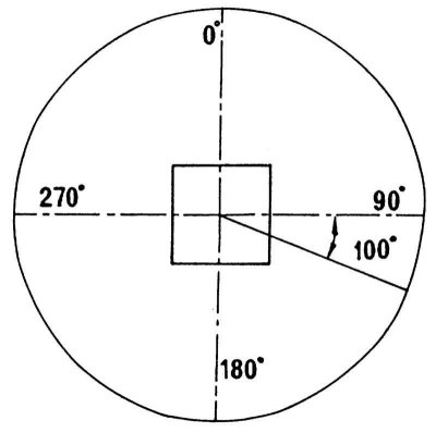
Type of homemade protractor. It should be used when tightening the cylinder head bolts.
- Put the template on the extension and insert the extension into the socket.
- Put the head on the bolt (10) (see illustration) and match the dot «0» with any point on the cylinder head.
- Now tighten the bolt until the 90 - 100°mark is reached.
- Tighten the rest of the bolts in the same way, keeping the angle as accurate as possible if possible.
- In the same way tighten the bolts by another 90 - 100°In no case should the bolts be tightened immediately by 180 - 200°, i.e. half a turn. Turning to a given angle should be carried out in two passes.
45. Screw in 4 bolts of a head of cylinders on outside.
46. On the SR20DE engine, install the water tube. Also on this engine, reinstall the starter.
47. Connect all water hoses. Check if hoses and clamps can be reused.
48. Clean the surface of the cover of the extreme bearing of the left camshaft from sealant residues and also clean the mounting side of the cylinder head from it. Then cover mating surfaces with sealant.
49. Lubricate the camshaft bearing journals well and insert into the bearing holes. Rotate the camshafts until the end surface guide pins are in the following position:
- The pin of the right shaft must be vertically up (12 hours)
- The pin on the left shaft must also point up (but at 10 o'clock)
50. Tighten the camshaft bearing caps now. This work is quite complex and must be carried out, guided by illustrations Camshaft bearing cap tightening sequence. Large cover refers to the left camshaft and The individual bolts mentioned in the text are marked with letters from A to D below. One illustration shows the tightening sequence, the other illustration shows different bolts that have different tightening torques. Proceed as follows:
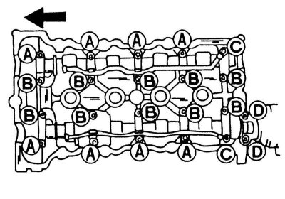
The individual bolts mentioned in the text are designated by letters A to D.
- When tightening the right camshaft, tighten the bolts (9) And (10) and then bolts (1) By (8) in a given sequence with a force of 2 Nm.
- When tightening the left camshaft, tighten the bolts (11) And (12) and then bolts (1) By (10) in a given sequence with a force of 2 Nm.
- Tighten all bolts in the above sequence to 6 Nm.
- Tighten all bolts indicated on illustrations letters A, B and C, in the above sequence with a force of 9 -12 Nm.
- Tighten all bolts indicated on illustrations letter D, with a force of 18 - 25 Nm.
51. Put on the camshaft sprockets (connecting with guide pins), while installing the chain. The marks on the sprockets and chain links must match, as seen from illustrations.
52. Screw in the bolts while holding the camshafts (see illustration) tighten the bolts with a force of 14-16 Nm.
53. Install the chain guide (6) (see illustration).
54. Install the ignition distributor. The intake spline in the camshaft must be horizontal. After installation, compare the distributor with illustration.
55. Install the chain tensioner. When doing this, follow the illustration to tension the tensioner. To do this, press the locking latch (1) inward and push the piston (2) into the tensioner until the hook (4) cannot be snapped over the pin (3). Screw the tensioner arrow to the front of the engine. After tightening the tensioner, the hook (4) is released and the tensioner automatically engages.
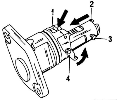
Elements for blocking the chain tensioner
1 - locking bracket; 2 - piston; 3 - pin; 4 - hook
56. Screw on the oil filter base and power steering pump console.
57. Establish support or a support of the inlet pipeline.
58. Remove all gasket residue from the sealing surfaces of the cylinder head and cylinder head cover and coat both surfaces with sealant.
59. Apply a gasket and tighten the fastening nuts in reverse order illustrations. Tighten the nuts in the middle first, starting with the nuts (4), (3), (1) And (6) with a force of 4 Nm. Then tighten all nuts in reverse order to 8 - 10 Nm. Again, the nut in the middle is tightened first.
60. Perform all other work in the reverse order of removal.