


Table of contents: Removal ↓ Installation ↓
Note: Reliable lifting equipment with approved rigging is required to perform engine removal and installation procedures.
Removal
The general appearance of the engine and the layout of the auxiliary equipment and units on it are shown in the accompanying illustrations.
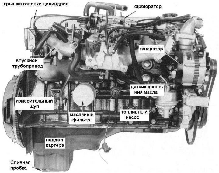
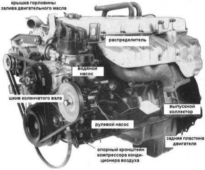
1. Raise the hood and ensure that the front body panels of the car are securely protected.
2. Mark the hood hinges with a marker to make installation easier. Disconnect the windshield washer fluid supply hose from the hood.
3. Loosen the mounting bolts and, with the help of an assistant, remove the hood from the car.
4. Disconnect the negative cable from the battery.
5. Drain the cooling system and remove the radiator and fan assemblies from the vehicle (see Chapter Cooling, heating and air conditioning systems).
6. Remove the air cleaner and air intake hose (see Chapter Fuel and exhaust systems).
7. Loosen the clamps securing the fuel supply and return hoses to the fuel pump. Disconnect the hoses. Plug the open ends of the hoses to prevent dirt from getting into the fuel system.
8. Disconnect the heating hoses from the pipes on the engine compartment bulkhead - try not to accidentally damage the latter. If necessary, cut the hoses to facilitate the procedure of their removal.
9. Loosen the throttle cable mounting nuts on the bracket, turn the lever to move the throttle to the fully open position and remove the end of the cable from the holder. Set the cable aside, laying it out of the way of further work.
10. Disconnect the brake booster and clutch servo vacuum hoses from the intake manifold.
11. Disconnect the main starter power wire and disconnect the electrical connector of the solenoid relay.
12. Disconnect the generator main wire terminal, disconnect the generator electrical connector. Loosen the generator ground wire mounting nut.
13. Disconnect the electrical connector located under the intake manifold for the oil pressure warning lamp and the gauge sensor.
14. Disconnect the electrical connector on the carburetor and disconnect the temperature sensor wiring. Remove the wiring harness from under the intake manifold and place it away from the work area.
15. Loosen the bolt and disconnect the ground wire from the engine oil dipstick guide tube bracket.
Note: If the transmission wiring harness is routed between the dipstick and the engine block, it will need to be repositioned to the opposite side of the dipstick to avoid snagging during engine removal.
16. On models equipped with air conditioning, disconnect the idle speed stabilizer vacuum hoses from the throttle damper and intake manifold.
17. On the left side of the engine compartment, disconnect the ground wires from the powertrain lifting eye and the ignition coil bracket.
18. Disconnect the distributor electrical connector and the air conditioning compressor clutch wiring connector (if included in the package).
19. Disconnect the carbon canister hoses from the steel pipes on the engine.
20. Place a drain pan under the steering pump, loosen the return hose clamp, disconnect the hose and drain the power steering fluid. Loosen the hollow bolt on the pump - be careful not to lose the copper sealing washers.
21. Tie the power steering hoses away from the work area and wrap them with a clean, lint-free cloth to prevent dirt from getting into the system.
22. Jack up the front of the car and place it on supports.
23. Loosen the bolts and release the plastic screw clamps securing the crankcase guard. Remove the guard.
24. On models equipped with air conditioning:
- Loosen the tension roller lock nut and, using a screwdriver to turn the adjusting bolt, remove the drive belt from the compressor pulley.
- Remove the lower compressor mounting bolts and nuts.
- Remove the upper mounting bolts, lift the compressor and secure it to the left fender splash guard.
Note: Do not loosen the compressor high pressure lines to avoid injury, frostbite, or damage from direct contact with the refrigerant. In addition, loss of refrigerant will require the system to be recharged.
25. Loosen the nuts securing the flange of the exhaust system's inlet pipe to the exhaust manifold, disconnect the inlet pipe without changing its position on the vehicle.
26. Loosen the clutch dome fastener to the engine plate. Unscrew the reinforcement bracket fastening bolts and remove the brackets from the engine.
27. Loosen the mounting bolts and remove the starter from the engine - you may have to overcome some resistance due to the need to break the sealant layer.
28. On models with AT, loosen the mounting bolts and remove the converter cover plate. Using a suitable lever, turn the engine by the drive disk so that one of the converter mounting bolts becomes accessible. After unscrewing the bolt, repeat the procedure for the remaining fasteners. Press the converter toward the transmission.
29. Raise the engine using suitable lifting equipment, removing the weight of the power unit from its supports.
30. Remove the nuts securing the engine mounts to the cylinder block and the bolts securing the mounts to the chassis.
31. Raise the engine slightly and remove the mounts. Lower the engine onto the chassis to allow easier access to the upper clutch dome mounting bolts.
32. Remove the upper bolts securing the clutch dome to the engine.
33. Using a thin knife or other suitable tool, cut the layer of sealant around the perimeter of the clutch dome, being careful not to damage the mating surfaces.
34. Carefully lift the engine assembly and slide it forward along the vehicle. On models with manual transmission, make sure that the transmission input shaft comes out of the clutch assembly freely. On models with automatic transmission, make sure that the rotation converter does not fall out of its housing.
35. Using extreme caution, being careful not to damage fragile components, remove the engine assembly from the vehicle. If there is the slightest uncertainty, it is worth taking the time to first remove any obstructing components.
Installation
Installation is generally carried out in reverse order.
1. Make sure the mating surfaces of the clutch dome and engine are thoroughly cleaned. Apply a bead of sealant to the dome flange.
Note: A tight fit between the backplate and the engine is also extremely important to prevent water leakage into the clutch dome.
2. On models with a manual transmission, do not forget to use a special tool to center the driven clutch disc on the flywheel, only then tighten the basket fasteners (see Chapter Clutch).
3. Before installing the front powertrain mounts, screw in the upper clutch dome engine mounting bolts.
4. After transferring the weight of the engine to the supports, tighten the bolts and nuts securing them to the chassis and engine.
5. Fill the engine with the required amount of oil of the required grade. Fill the cooling system (see Chapter Cooling, heating and air conditioning systems).
6. Connect the exhaust pipe to the exhaust manifold using a new gasket.
7. Lubricate the starter mounting flange with sealant and install the starter in its place.
8. Adjust the throttle cable (see Chapter Fuel and exhaust systems).
9. Before starting the engine for the first time, check that all settings are correct and that the drive belt tension is adjusted.
10. After starting, monitor the engine temperature and oil pressure. Check the engine for leaks, and if any are found, eliminate their causes.
Late-model 4.2 L models equipped with fuel injection (EFI)
The removal and installation procedures for 4.2L engines equipped with EFI are basically identical to those for carbureted engines, with the exception of the following points.
1. Before disconnecting the battery, it is necessary to relieve the pressure in the fuel system, for which:
- Loosen the screws and lift up the relay panel located in the engine compartment next to the battery. Remove the cover and take out the 15A fuel pump fuse;
- Start the engine and let it idle until it stops on its own. To ensure complete pressure relief, turn on the starter for 10 seconds;
- Turn off the ignition.
2. Remove the air duct and muffler installed between the throttle body and the air flow meter.
3. Instead of disconnecting the fuel lines from the fuel pump, loosen the clamps and disconnect the fuel return line from the fuel pressure regulator and the fuel supply line from the fuel line.
4. In addition to the generator, also disconnect the wiring from the air regulator located under the right front corner of the intake manifold. Disconnect the main ground bus from the bracket at the front of the intake manifold, and disconnect the ground wires from the wall of the manifold.
5. Instead of disconnecting the wiring from the carburetor and temperature sensor, disconnect the three electrical connectors located on the bracket at the front of the intake manifold.
6. Skip the procedure for disconnecting the idle speed control vacuum hoses on models equipped with air conditioning.
Note: Remember to label all wires and hoses before disconnecting them.
7. Perform installation in reverse order, taking into account the following points:
- Make sure that no wires, cables or hoses are pinched during installation of the unit.
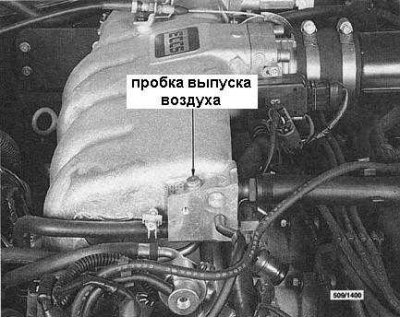
- When filling the cooling system, pay attention to the presence of an air release plug located in the front part of the air duct pressure chamber, as on models with a 3.0 L engine (see accompanying illustration).
- Installation of the radiator on 4.2 L EFI engines is the same as on 3.0 L engines.