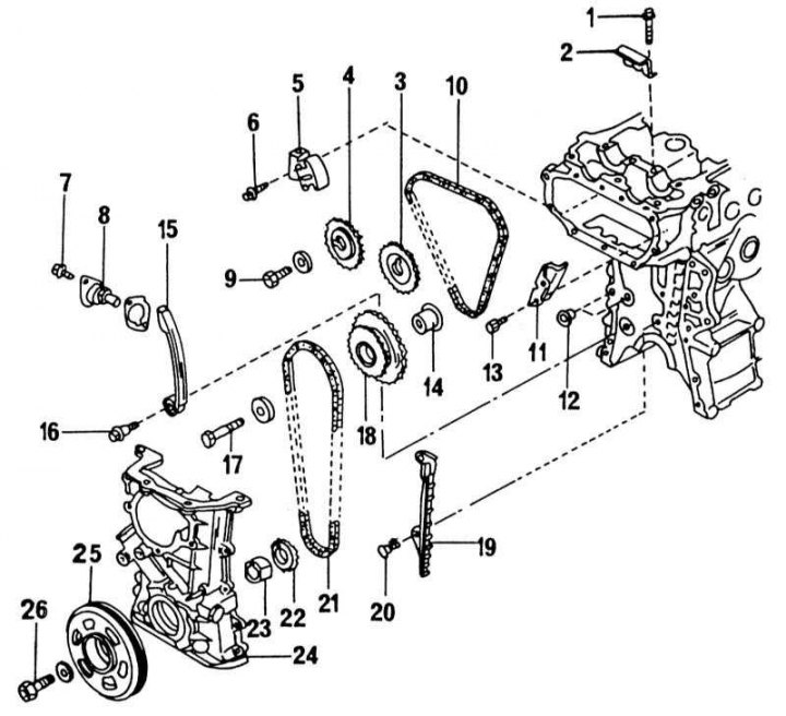
Elements of the drive mechanism of the carburetor engine
1 - bolt, 9-12 Nm; 2 - chain guide; 3 - exhaust camshaft sprocket; 4 - intake camshaft sprocket; 5 - chain tensioner; 6 - bolt, 6-8.5 Nm; 7 - bolt, 6-12 Nm; 8 - chain tensioner; 9 - bolt, 100-130 Nm; 10 - upper chain; 11 - chain guide; 12 - round seal; 13 - bolt, 6-8.5 Nm; 14 - intermediate sprocket shaft; 15 - chain tensioner bar; 16 - support pin, 13-19 Nm; 17 - bolt, 45-60 N·m; 18 - intermediate sprocket; 19 - chain guide; 20 - bolt, 13-19 Nm; 21 - lower drive chain; 22 - crankshaft sprocket; 23 - remote element of the oil pump; 24 - camshaft drive cover; 25 - belt pulley; 26 - bolt, 135-155 Nm
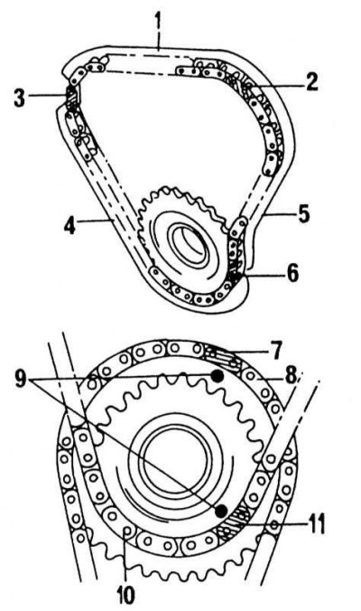
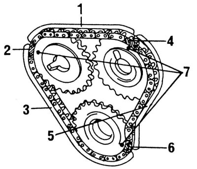
The position of the marks of the upper and lower chains
1 - 16 links between marks (2) And (3); 2 - chain label (silver color); 3 - chain label (silver color); 4 - 22 links between marks (3) And (6); 5 - 16 links between notches (2) And (6); 6 - chain label (silver color); 7 - label of the lower chain (silver color); 8 - lower drive chain; 9 - mark on the intermediate shaft sprocket; 10 - upper chain; 11 - label of the lower chain (silver color)
1. Unscrew all panels installed under the front of the car.
2. Place the front on supports, unscrew the right wheel and unscrew the shield in the front right wheel arch.
3. Drain the coolant as described in Chapter Cooling and heating systems.
4. Remove the alternator and power steering pump drive belts. Unscrew the pump together with the console from the engine. Do not disconnect hoses.
5. Completely remove a reception pipe of the muffler.
6. Attach the engine with cables to the lift and remove the front engine mount. This is the bracket shown in illustrations.
7. Remove all spark plugs.
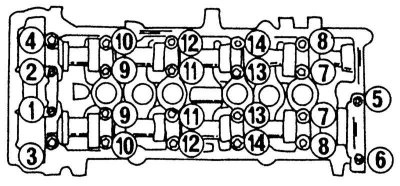
8. Remove the cylinder head cover. In order not to overtighten the cover when loosening, a certain sequence must be followed. It is shown in the illustration below.
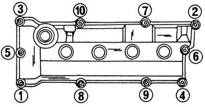
Cylinder head cover bolt loosening sequence.
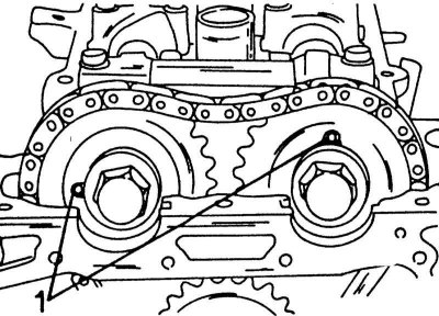
9. Turn the crankshaft (putting the socket head on the crankshaft belt pulley bolt), until the mark on the belt pulley is opposite the pointer on the timing cover (see illustration below). In this position of the crankshaft, the piston of the 1st cylinder is in the TDC position of the end of the compression stroke.
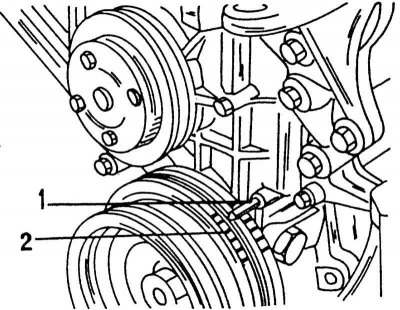
When the piston of the 1st cylinder is in the TDC position, the pointer (1) and label "0" on belt pulley (2) must match.
10. Remove the distributor cap and inspect the distributor head. The slider must be in the position shown in illustrations. To remember this position for installation, you should draw a line on the edge of the distributor housing opposite the middle of the slider. Then remove the ignition distributor.
11. Unscrew the camshaft sprocket cover.
12. Remove the water pump pulley.
13. Remove the thermostat housing.
14. Remove the chain tensioner. It is secured with two bolts.
15. Based on the illustration below, check that both control marks on the camshaft sprockets are opposite each other. Then remove the inner chain tensioner on the left side and the chain guide on the right side.
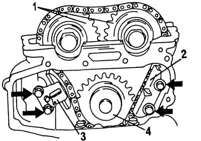
View of installed sprockets, tensioner and chain guide. Arrows indicate mounting bolts
1 - control marks of camshaft sprockets; 2 - chain guide; 3 - chain tensioner; 4 - intermediate sprocket
16. Loosen and remove the camshaft sprocket bolts. In this case, the shafts must be kept from turning. Remove both sprockets while removing the chain. Do not turn the camshafts again, otherwise the valves will hit the pistons. If only the cylinder head needs to be removed, tighten the chain and tie it.
17. Loosen the camshaft bearing cap bolts in several passes in the sequence shown in the illustration. Mark the position of the covers and remove them. Remove both distributors.
Camshaft bearing cap loosening sequence.
18. Loosen the cylinder head bolts starting from the edges to the middle in several passes in the sequence shown in the illustration and remove the cylinder head. The intake manifold and exhaust manifold remain on the cylinder head. If the head is stuck to the gasket, you can tap it with a rubber mallet. Never attempt to remove the head by inserting a screwdriver between the sealing surfaces. Carefully place the cylinder head on a workbench if it is to be disassembled or repaired.
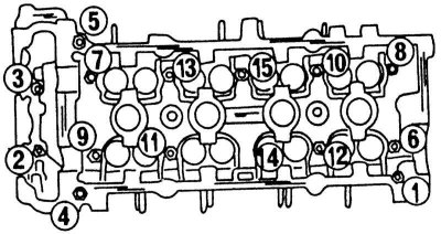
Cylinder head bolt loosening sequence.
19. From the reverse side, remove the intermediate sprocket shaft.
20. Remove the top drive chain.
21. Check that the engine is securely hanging on the lift and remove the middle beam of the engine.
22. Remove the oil pan and oil suction screen (Chapter Removal and installation of the oil pan).
23. Keeping the crankshaft from turning (turn on the transmission) loosen the crankshaft pulley bolt. Press out the pulley with two pry bars.
24. Place a mobile jack under the engine and raise the engine. Place a piece of wood between the lift and the engine. Unscrew the front engine mount from the suspension.
25. Unscrew a cover of a drive of the distributive mechanism. One bolt is inserted into the water pump.
26. Remove the parts from the end of the engine shown in the illustration below.
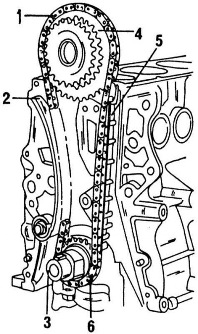
View of the lower chain installed
1 - lower drive chain; 2 - chain guide; 3 - remote ring of the oil pump drive; 4 - intermediate sprocket; 5 - chain guide; 6 - crankshaft sprocket
27. Installation of the camshaft drive and cylinder head is carried out in the following sequence. On illustrations individual elements of the timing gear drive with tightening torques are shown.
28. Check that the piston of the 1st cylinder is in the TDC position. Both keys in the crankshaft must be vertical.
29. Install the chain guide.
30. Hammer in the crankshaft sprocket and apply the lower drive chain. The sprocket is marked and the silver link should fit on the marked prong.
31. The asterisk must be installed with the label facing out. The other silver link is symmetrical so that the chain can be applied in any way. Stretch the chain and tie at the top so that it cannot slip off.
32. Install the timing gear cover:
- Coat the surface of the cover with sealant.
- Check again that the marks on the chain and sprocket match.
- Align the oil pump drive spacer with the pump.
- Press the chain against one side of the guide so that it cannot touch the cover seal.
- Insert two new O-rings inside the cover.
- When installing the cover, be careful not to damage the seal.
33. Install the front engine mount.
34. Install the oil suction screen and oil pan (Chapter Removal and installation of the oil pan).
35. Install the crankshaft pulley and tighten the bolt.
36. Install the middle beam of the engine (see illustration).
37. Align the large countershaft sprocket so that the mark on the sprocket aligns with the silver chain link. Then, guided illustration, place the top chain so that the mark on the small sprocket aligns with the silver link on the top chain.
38. Both marks on the intermediate shaft sprockets must face outwards. Insert the intermediate sprocket shaft from the rear.
39. Install the cylinder head with a new gasket. Washers are superimposed on the cylinder head bolts, with the flat side facing the head. Install the head with the inlet pipe and exhaust manifold and besiege with a rubber mallet. Screw in all bolts.
40. Tighten the cylinder head bolts in the reverse order to that shown in illustrations. Lubricate the bolt threads, the underside of the bolt heads and washers with oil and tighten all bolts by hand.
41. The bolts are tightened as follows:
42. Tighten all bolts according to the diagram on illustrations with a force of 29 Nm.
43. Tighten all bolts according to the diagram on illustrations with a force of 60 Nm.
44. Loosen all bolts completely.
45. Tighten all bolts in accordance with the diagram in illustration 4.78 with a force of 30 Nm.
46. Tighten all bolts to the specified angle in the sequence shown on illustrations.
47. All bolts should be tightened by an angle of 50 - 55°. To properly maintain the angle, you need a template that you should make yourself. Cut out a cardboard circle and divide it into four equal 90°segments. Divide one of the segments to get a 45°angle. Mark the area 50 - 55°below the 45°line as shown in the illustration. Exactly in the middle of the template, cut a square hole the size of the socket and extension used. When tightening, proceed as follows:
- Put the template on the extension and insert the extension into the socket.
- Put the head on the bolt (15) (see illustration) and match the dot «0» with any point on the cylinder head.
- Now tighten the bolt until the 50 - 55°mark is reached
- Tighten the rest of the bolts in the same way, keeping the angle as accurate as possible if possible.
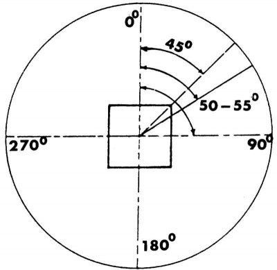
View of a homemade corner template for a carburetor engine.
48. If you do not use a template, you can tighten the bolts to 60 Nm after they have been tightened to 30 Nm. Then tighten the bolts from the outside (bolts 1 to 5 on illustrations) with a force of 6.5 - 8.5 Nm.
49. Block the chain drive and tighten the idler gear bolt.
50. Install the camshafts, camshaft bearing caps and ignition distributor. Tighten the camshaft bearing cap bolts in the reverse order to that shown illustrations. Lubricate the camshaft bearing journals well. After replacing valve parts or camshafts, the valve clearance should be adjusted as described below.
51. Insert the camshaft sprockets into the chain and screw them onto the shafts. At the same time, guided by the illustration, and count the number of links between the silver links on the upper side. Each sprocket has one notched prong that must be inserted into the silver link. Also, the mark on the countershaft sprocket must be properly aligned as shown in the illustration, i.e. the marks on the camshaft and countershaft sprocket must line up with the silver links. The guides inside the camshaft sprockets will be in the position shown.
Properly assembled top drive chain with sprockets installed
1 - 16 links; 2 - left label; 3 - 22 links; 4 - right label; 5 - 16 links; 6 - bottom mark; 7 - marks on asterisks
52. Carefully rotate both camshafts (the crankshaft must also rotate so that the valves cannot hit the pistons), until both guide pins are in the position shown in the illustration. In this position, put the sprockets on the shafts (the pins must fit into the guides in the asterisks) and insert the bolts. Tighten the bolts to the required torque. Check again that the labels in the illustration below match.
Both drive pins must be in the position shown before the sprockets are put on them.
53. Install the internal chain tensioner and chain guide according to illustrations. Check that the tensioner lock hook is free.
54. Screw in the chain tensioner from the outside. Rotate the crankshaft slowly to check that the crankshaft drive can rotate freely. Set the piston of the 1st cylinder to the TDC position.
55. Lubricate the gasket of the thermostat housing with sealant and screw it on.
56. Screw on the water pump pulley.
57. Install the ignition distributor. The receiving slot on the end of the camshaft must be horizontal.
58. Screw on the camshaft sprocket cover.
59. Lubricate the semi-circular seals with a 3 mm wide strip of sealant and insert the cylinder heads into the beds. Align them well so that the top side is flush with the surface of the cylinder head.
60. Coat the cylinder head cover gasket with sealant and install the cover.
61. Tighten the bolts in the reverse order to that shown in illustrations.
62. Perform all other work in the reverse order of removal.