Preparatory work
(see details in para. «Preparatory work» relevant sections)
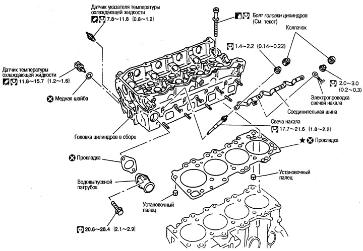
Drain the coolant, remove the intercooler, valve cover, vacuum pump, rear cylinder head cover assembly, high pressure fuel pipes, drain pipe, fuel injector assemblies, timing chain, camshafts, catalyst, exhaust manifold, turbocharger and intake manifold.
Removal and installation of a head of cylinders
Removing
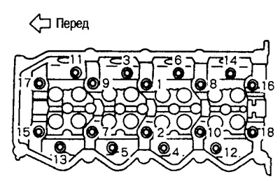
Loosen the set screws in the reverse order of the illustration.
Attention: Because Glow plugs protrude from the underside of the cylinder head, remove the cylinder head taking care not to damage the glow plugs. You can put the cylinder head by placing a board under it.
Installation
1. Tighten the set bolts in the order shown in the figure as follows.
(1) Lubricate the threaded parts and seating surface of the mounting bolts with engine oil.
(2) Tighten the bolts to 28.4-38.2 Nm (2.9-3.9 kg m).
(3) Tighten bolts 180-185° (norm 180°).
(4) Loosen the bolts to 0 Nm (0 kg m).
Attention: Loosening the bolts according to par. (4) performed in the reverse order shown in the figure.
(5) Tighten the bolts to 34.3-44.1 Nm (3.5-4.5 kg m).
(6) Tighten 90-95° (norm 90°).
(7) Retighten 90-95° (norm 90°).
Attention: Determine the angle of rotation of the bolt in accordance with point 2. Do not make an assessment of the tightening angle «approximately».
Installing the cylinder head (determination of tightening angle)
Tighten the bolts to a certain angle as follows. (Clause 1, paras. (3), (6), (7)).
Angle tightening using a protractor
The tightening angle is determined by the marks on the cylinder head and on the bolt heads.
Tightening with protractor wrench
The tightening angle is determined by the scale of the protractor key.
Installing the cylinder head
Apply Tree Bond 1207C in a continuous bead (KR510 00150) to the areas shown in the figure.
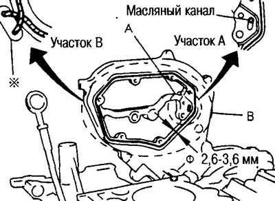
Pay special attention when applying sealant to the following areas.
- A: Apply sealant so that it does not extrude into the oil passage.
- B: Do a minimal overlap of sealant strips at the junction of the beginning and end of the strip. The area marked with * is outside and after assembling the engine this place is not visible.
Selection of cylinder head gasket
Select the gasket as follows.
In case of gasket replacement
Install a gasket of the same thickness.
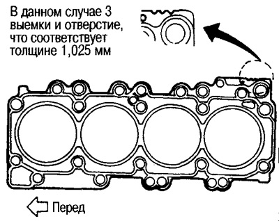
Gaskets are marked by thickness using recesses and holes on the right rear side of the gasket.
Note: Specifies the gasket thickness obtained after tightening the cylinder head set bolts.
The thickness of the gasket can be determined before removing the cylinder head from the above grooves and hole.
In case of repair and replacement of parts
When grinding the upper surface of the cylinder block, grinding the main or connecting rod journals of the crankshaft, select the gasket in the following order.
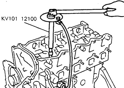
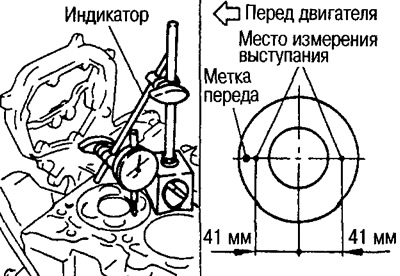
(1) Set the piston to TDC.
(2) Install the indicator in the places shown in the figure, slowly turn the crankshaft, set the indicator to zero reading at the maximum piston lift.
(3) Move the indicator stand, place the indicator on the cylinder block and read off the reading.
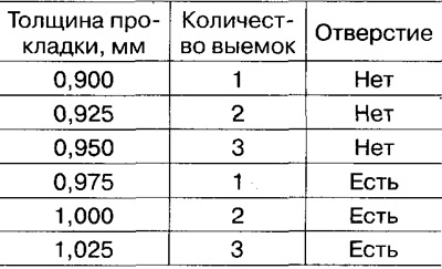
(4) Take a measurement on each cylinder at two points, select the maximum piston protrusion and select the required gasket from the table.
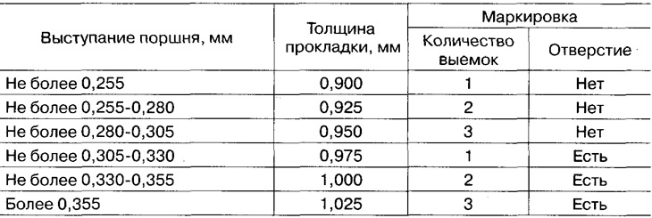
Note: Specifies the gasket thickness obtained after tightening the cylinder head set bolts.
Removal and installation of glow plugs
Attention:
Do not remove candles unnecessarily, because. they may break.
Check spark plugs for conductivity when installed.
Don't damage the candles (if the candle is dropped from a height of more than 10 cm, replace).
Installation
Install glow plugs after removing carbon deposits in the mounting holes using a reamer.
Installing the coolant temperature sensor and temperature gauge sensor
Apply Three Bond 1386B Sealant to threaded areas before installing sensors.
Examination
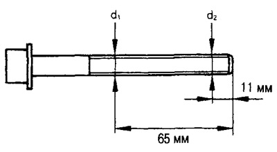
Deformation check (sprains) cylinder head set bolts
Using a micrometer, measure the diameters d1, d2 threaded section of the bolt.
If it is possible to determine the narrowed place, then measure the diameter d, at this place.
Calculate the difference between d1 and d2.
- Limit difference: 0.15mm
Checking levels between cylinder head and cylinder block
After installing the cylinder head, measure the distance between the front surface of the cylinder block and the front surface of the cylinder head.
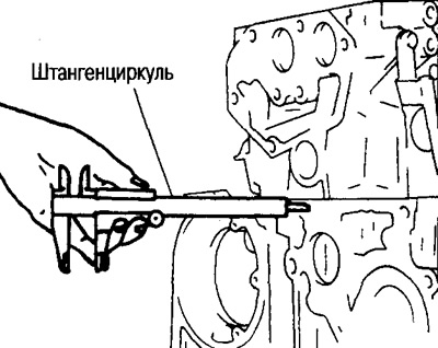
- Standard distance: 23.8+0.27mm
If the distance is different from the standard, re-install.