


Diesel engine YD25DDTi cars Nissan Serena 2 (C24)

Service by car
Air cleaner element Replacement interval: every 60,000 km. Compression 1. Warm up the engine to operating temperature and shut it off. 2. Verify that there are no faults...
Air cleaner element Replacement interval: every 60,000 km. Compression 1. Warm up the engine to operating temperature and shut it off. 2. Verify that there are no faults...

Drive belts — check
The check is performed on a cold engine or 30 minutes or more after the engine has stopped. Visually check for damage on the outer and inner sides of the belts along...
The check is performed on a cold engine or 30 minutes or more after the engine has stopped. Visually check for damage on the outer and inner sides of the belts along...

Drive Belts — Adjustment
Make the adjustment as follows. Attention: After replacing the belt with a new one, slightly increase the tension of the new belt compared to the old one to allow for...
Make the adjustment as follows. Attention: After replacing the belt with a new one, slightly increase the tension of the new belt compared to the old one to allow for...

Drive belts — removal and installation
Removing the straps 1. Remove the right engine protection from the bottom. 2. Loosen all straps (see above section «Adjustment») and remove the A/C compressor belt, then...
Removing the straps 1. Remove the right engine protection from the bottom. 2. Loosen all straps (see above section «Adjustment») and remove the A/C compressor belt, then...

Air cleaner and air duct — removal and installation
Preparatory work Remove the mass air flow sensor harness connector. Remove left fender guard (if the resonator located under the wing is removed). Removal and...
Preparatory work Remove the mass air flow sensor harness connector. Remove left fender guard (if the resonator located under the wing is removed). Removal and...

Intercooler — removal and installation
Removing Disconnect from bottom bracket. Caution: After removing the intercooler, cover the open holes on the turbocharger side and on the intake manifold side with a...
Removing Disconnect from bottom bracket. Caution: After removing the intercooler, cover the open holes on the turbocharger side and on the intake manifold side with a...
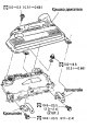
Intake manifold — removal and installation
Preparatory work Drain the coolant. Remove the air cleaner housing and air duct. Remove the intercooler. Remove the engine cover (see point 1). Remove the intercooler...
Preparatory work Drain the coolant. Remove the air cleaner housing and air duct. Remove the intercooler. Remove the engine cover (see point 1). Remove the intercooler...

Intake manifold — check
Checking the intake manifold for warping Connect the hand vacuum pump to the drive, close the control valve. swirl of air, pumping out air. Use a ruler and feeler gauge...
Checking the intake manifold for warping Connect the hand vacuum pump to the drive, close the control valve. swirl of air, pumping out air. Use a ruler and feeler gauge...

Catalyst — removal and installation
Preparatory work Remove the engine protection from the bottom. Drain the coolant. Remove the radiator fans assembly. Remove the water inlet tube. Removal and...
Preparatory work Remove the engine protection from the bottom. Drain the coolant. Remove the radiator fans assembly. Remove the water inlet tube. Removal and...
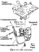
Exhaust manifold and turbocharger — removal and installation
Preparatory work Removal and installation of a final collector in gathering Drain the coolant. Remove the air cleaner and air intake tube. Remove the intercooler. Remove...
Preparatory work Removal and installation of a final collector in gathering Drain the coolant. Remove the air cleaner and air intake tube. Remove the intercooler. Remove...

Exhaust manifold and turbocharger — check
Exhaust manifold warping Use a ruler and feeler gauge to check the mounting surface for warping. Limit Warping: 0.3mm
Exhaust manifold warping Use a ruler and feeler gauge to check the mounting surface for warping. Limit Warping: 0.3mm

Exhaust manifold and turbocharger — disassembly and assembly
Removal and installation of a turbocharger Removing Lubricate the set bolts with a rust remover and, after impregnation, loosen and unscrew them. Caution: Do not...
Removal and installation of a turbocharger Removing Lubricate the set bolts with a rust remover and, after impregnation, loosen and unscrew them. Caution: Do not...

Checking turbocharger parts
Test sites and site names are shown in the figure on the next page. Attention: In case of breakage of the compressor wheel, turbine wheel, rotor shaft, remove foreign...
Test sites and site names are shown in the figure on the next page. Attention: In case of breakage of the compressor wheel, turbine wheel, rotor shaft, remove foreign...

Valve cover — removal and installation
Preparatory work Remove the intercooler. Remove the engine cover. Removal and installation of a valvate cover Removing Loosen the set screws in the reverse order of the...
Preparatory work Remove the intercooler. Remove the engine cover. Removal and installation of a valvate cover Removing Loosen the set screws in the reverse order of the...

Vacuum pump — removal
1. Remove the following parts. Air cleaner housing and air duct, intercooler, engine cover, valve cover, move the boat ventilation hose to the side, remove the exhaust...
1. Remove the following parts. Air cleaner housing and air duct, intercooler, engine cover, valve cover, move the boat ventilation hose to the side, remove the exhaust...

Vacuum Pump — Installation
1. Assemble the vacuum pump with rear cylinder head cover (see below section « Assembly »). 2. Install vacuum pump with rear cylinder head cover assembly. (1) Apply...
1. Assemble the vacuum pump with rear cylinder head cover (see below section « Assembly »). 2. Install vacuum pump with rear cylinder head cover assembly. (1) Apply...

Vacuum pump — check
Remove the vacuum hose, install the tee and connect the vacuum gauge (special tool). Install the tee in a location where you can directly read the reading (the figure...
Remove the vacuum hose, install the tee and connect the vacuum gauge (special tool). Install the tee in a location where you can directly read the reading (the figure...

Vacuum pump — disassembly and assembly
Disassembly Assembly Install all parts on the rear cylinder head cover in the following order. 1. Install the vacuum pump. 2. Install the chain tensioner. Tension...
Disassembly Assembly Install all parts on the rear cylinder head cover in the following order. 1. Install the vacuum pump. 2. Install the chain tensioner. Tension...

Oil pan, oil pre-filter — removal and installation
Preparatory work (*: removing components from above) Drain the engine oil. Remove the engine protection from the bottom. Remove the right mudguard. Remove the front...
Preparatory work (*: removing components from above) Drain the engine oil. Remove the engine protection from the bottom. Remove the right mudguard. Remove the front...

Starter — removal and installation
Removing 1. Remove the air cleaner and air duct. 2. Disconnect the automatic transmission control cable from the top of the starter, move the electrical wiring of the...
Removing 1. Remove the air cleaner and air duct. 2. Disconnect the automatic transmission control cable from the top of the starter, move the electrical wiring of the...

High pressure fuel pipes and injectors assy — removal and installation
Preparatory work Remove the intercooler, engine cover, underbody protection, front exhaust pipe. Disconnect all electrical wiring, all tubes and hoses and move aside....
Preparatory work Remove the intercooler, engine cover, underbody protection, front exhaust pipe. Disconnect all electrical wiring, all tubes and hoses and move aside....

High pressure fuel lines and injectors assemblies — check
Checking the tightness of the drain tube Check before installing the valve cover. Connect the vacuum pump to the drain tube. Create a vacuum and make sure it is kept...
Checking the tightness of the drain tube Check before installing the valve cover. Connect the vacuum pump to the drain tube. Create a vacuum and make sure it is kept...

High pressure fuel pump (TNVD) with electronic control — device
Attention: The electronically controlled injection pump cannot be disassembled. Note: Hereinafter, the electronically controlled high pressure fuel pump will be...
Attention: The electronically controlled injection pump cannot be disassembled. Note: Hereinafter, the electronically controlled high pressure fuel pump will be...

Injection pump — removal
1. Remove the following parts: Engine protection from the bottom and left mudguard front exhaust pipe Disconnect the right drive shaft from the side of the transfer case...
1. Remove the following parts: Engine protection from the bottom and left mudguard front exhaust pipe Disconnect the right drive shaft from the side of the transfer case...

Injection pump — installation
There is no need to adjust the injection timing by changing the installation angle, as in the old injection pumps, so it is enough to install the injection pump on the...
There is no need to adjust the injection timing by changing the installation angle, as in the old injection pumps, so it is enough to install the injection pump on the...

Secondary timing chain — removal
If the secondary timing chain is removed to remove the injection pump, see the preparatory work above in the section « injection pump with electronic control ». If the...
If the secondary timing chain is removed to remove the injection pump, see the preparatory work above in the section « injection pump with electronic control ». If the...
Secondary Timing Chain — Installation
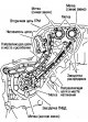
The figure shows the secondary timing chain, related parts and their names. 1. Install the secondary timing chain tensioner. Install by lining up the sprocket marks with...
The figure shows the secondary timing chain, related parts and their names. 1. Install the secondary timing chain tensioner. Install by lining up the sprocket marks with...

Primary timing chain — removal
1. Remove the engine with gearbox assembly (see section « Removing the engine »). 2. Separate the engine from the gearbox and place the engine on a stand (special tool)...
1. Remove the engine with gearbox assembly (see section « Removing the engine »). 2. Separate the engine from the gearbox and place the engine on a stand (special tool)...

Primary Timing Chain — Installation
1. Install the rear chain cover. Install next. manner. (1) Apply Three Bond 1207C in a continuous bead (KR510 00150) to the areas shown in the figure. In areas marked...
1. Install the rear chain cover. Install next. manner. (1) Apply Three Bond 1207C in a continuous bead (KR510 00150) to the areas shown in the figure. In areas marked...

Camshafts — device
Note: The camshafts on this engine are different from conventional DOHC. The following abbreviations are used in this section. Right camshaft: camshaft located on the...
Note: The camshafts on this engine are different from conventional DOHC. The following abbreviations are used in this section. Right camshaft: camshaft located on the...

Camshafts — removal
1. Remove the following parts and assemblies. Engine protection from the bottom front exhaust pipe Air duct and air cleaner housing Intercooler engine cover valve cover...
1. Remove the following parts and assemblies. Engine protection from the bottom front exhaust pipe Air duct and air cleaner housing Intercooler engine cover valve cover...

Camshafts — check
Visual inspection of the camshaft Check for nicks and wear. If defects are found, replace the camshaft. Camshaft runout Place the camshaft on prisms under the main...
Visual inspection of the camshaft Check for nicks and wear. If defects are found, replace the camshaft. Camshaft runout Place the camshaft on prisms under the main...

Camshafts — Installation
1. Install the valve lifters and shims. Install each part in its original place. 2. Install the camshafts. The difference between the camshafts is determined by the...
1. Install the valve lifters and shims. Install each part in its original place. 2. Install the camshafts. The difference between the camshafts is determined by the...

Checking valve clearances
The check is performed in case of replacement of parts related to camshafts or valves, as well as in case of abnormal operation of the engine caused by a change in valve...
The check is performed in case of replacement of parts related to camshafts or valves, as well as in case of abnormal operation of the engine caused by a change in valve...

Valve clearance adjustment
Remove the adjusting washer of the valve whose clearance is not correct. 1. Remove the drain tube. 2. Carefully wipe off the oil on top of the cylinder head with a rag...
Remove the adjusting washer of the valve whose clearance is not correct. 1. Remove the drain tube. 2. Carefully wipe off the oil on top of the cylinder head with a rag...

Cylinder head — removal and installation
Preparatory work (see details in para. «Preparatory work» relevant sections) Drain the coolant, remove the intercooler, valve cover, vacuum pump, rear cylinder head...
Preparatory work (see details in para. «Preparatory work» relevant sections) Drain the coolant, remove the intercooler, valve cover, vacuum pump, rear cylinder head...

Cylinder head — disassembly
1. Remove shims and valve lifters. Mark the installation location and store the parts so that they are not mixed up during subsequent installation. 2. Remove crackers....
1. Remove shims and valve lifters. Mark the installation location and store the parts so that they are not mixed up during subsequent installation. 2. Remove crackers....

Cylinder head — check
Warping of the cylinder head Check for warpage on the underside of the cylinder head at several points in six directions. Limit Warping: 0.04mm Valve sizes Use a...
Warping of the cylinder head Check for warpage on the underside of the cylinder head at several points in six directions. Limit Warping: 0.04mm Valve sizes Use a...

Cylinder head — assembly
1. If valve guides were removed, install them (see section « Valve guide clearance »), 2. If the valve seats were removed, install them. 3. Install valve seals. Install...
1. If valve guides were removed, install them (see section « Valve guide clearance »), 2. If the valve seats were removed, install them. 3. Install valve seals. Install...

Removing the engine
Attention: Follow the safety rules and do not do unnecessary actions. Do not start work until the exhaust system and cooling system have completely cooled down. When...
Attention: Follow the safety rules and do not do unnecessary actions. Do not start work until the exhaust system and cooling system have completely cooled down. When...

Engine installation
Installation is carried out in the reverse order of removal, taking into account the following. Be careful not to get oil on the insulators, and do not damage the...
Installation is carried out in the reverse order of removal, taking into account the following. Be careful not to get oil on the insulators, and do not damage the...

Engine check
Before starting the engine, check the level of coolant, lubricating oils, power steering oil and top up if necessary. Start the engine and check for abnormal sounds and...
Before starting the engine, check the level of coolant, lubricating oils, power steering oil and top up if necessary. Start the engine and check for abnormal sounds and...
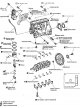

Cylinder Block — Component Selection Order
Since the markings on a part reflect its original dimensions, do not refer to them if the part is being reused. Recycled and machined parts must be sized and graded. For...
Since the markings on a part reflect its original dimensions, do not refer to them if the part is being reused. Recycled and machined parts must be sized and graded. For...

Cylinder block — disassembly
1. Remove the engine with gearbox and suspension beam assembly and separate the engine from the gearbox and suspension beam (see section « Removal and installation of...
1. Remove the engine with gearbox and suspension beam assembly and separate the engine from the gearbox and suspension beam (see section « Removal and installation of...

Axial backlash of the crankshaft — check
Use a dial gauge to measure the clearance between the thrust bearing and the crank arm by moving the crankshaft back and forth. Standard backlash: 0.10-0.25 mm Limit...
Use a dial gauge to measure the clearance between the thrust bearing and the crank arm by moving the crankshaft back and forth. Standard backlash: 0.10-0.25 mm Limit...

Lateral clearance in the connecting rod — check
Using a feeler gauge, measure the clearance between the connecting rod and the crank arm. Standard: 0.200-0.350mm Limit: 0.4mm If the measured clearance is greater than...
Using a feeler gauge, measure the clearance between the connecting rod and the crank arm. Standard: 0.200-0.350mm Limit: 0.4mm If the measured clearance is greater than...

Gap between piston and piston pin — check
Piston bore inner diameter Measure the inside diameter of the piston pin bore using a bore gauge. Standard diameter: 27.997-28.005 mm Piston pin outer diameter Using a...
Piston bore inner diameter Measure the inside diameter of the piston pin bore using a bore gauge. Standard diameter: 27.997-28.005 mm Piston pin outer diameter Using a...

Lateral clearance in piston rings
Use a feeler gauge to measure the backlash between the piston ring and the ring groove. Standard Clearance: Top compression ring: 0.05-0.09mm Second compression ring:...
Use a feeler gauge to measure the backlash between the piston ring and the ring groove. Standard Clearance: Top compression ring: 0.05-0.09mm Second compression ring:...

The gap in the piston ring lock
Make sure the cylinder is the correct size (see section « Clearance between piston and cylinder »). Install the piston ring in the cylinder, push the ring to the middle...
Make sure the cylinder is the correct size (see section « Clearance between piston and cylinder »). Install the piston ring in the cylinder, push the ring to the middle...

Bending and twisting of the connecting rod
Check with a connecting rod alignment tool. Ultimate bending: 0.12 mm (per 100 mm length) Ultimate torsion: 0.12 mm (per 100 mm length)
Check with a connecting rod alignment tool. Ultimate bending: 0.12 mm (per 100 mm length) Ultimate torsion: 0.12 mm (per 100 mm length)

Big end hole diameter
Install the connecting rod cap without bearing, tighten to standard torque, and measure the inside diameter of the hole in the large end of the connecting rod. Standard...
Install the connecting rod cap without bearing, tighten to standard torque, and measure the inside diameter of the hole in the large end of the connecting rod. Standard...

Oil clearance in the bushing of the small head of the connecting rod
Connecting rod inner diameter Using an inside gauge, measure the inside diameter of the small end of the connecting rod. Standard Diameter: 28.026-28.038mm Piston pin...
Connecting rod inner diameter Using an inside gauge, measure the inside diameter of the small end of the connecting rod. Standard Diameter: 28.026-28.038mm Piston pin...

Warping of the upper surface of the cylinder block
Use a scraper to remove the remnants of the old gasket, oil, carbon deposits, etc. from the contact surface of the cylinder block. Caution: Do not allow sealant residue...
Use a scraper to remove the remnants of the old gasket, oil, carbon deposits, etc. from the contact surface of the cylinder block. Caution: Do not allow sealant residue...

Main bearing housing inner diameter
Install main bearing caps without bearings and tighten mounting bolts to specification. Using an inside gauge, measure the inside diameter of the main bearing housing....
Install main bearing caps without bearings and tighten mounting bolts to specification. Using an inside gauge, measure the inside diameter of the main bearing housing....

Clearance between piston and cylinder
Cylinder inner diameter Using a bore gauge, check each cylinder for wear, out-of-roundness and taper at 6 different X and Y positions at A, B and C (top, center and...
Cylinder inner diameter Using a bore gauge, check each cylinder for wear, out-of-roundness and taper at 6 different X and Y positions at A, B and C (top, center and...

Pistons selection procedure
When a new cylinder block is used Check the cylinder class on the rear left side of the cylinder block (1, 2 or 3) and select pistons of the same class. Note: Pistons...
When a new cylinder block is used Check the cylinder class on the rear left side of the cylinder block (1, 2 or 3) and select pistons of the same class. Note: Pistons...

Crankshaft journal diameters
Crankshaft journal diameter Using a micrometer, measure the diameter of the crankshaft main journal. Standard diameter: 62.951-62.975mm Crankshaft journal diameter Using...
Crankshaft journal diameter Using a micrometer, measure the diameter of the crankshaft main journal. Standard diameter: 62.951-62.975mm Crankshaft journal diameter Using...

Ovality and taper of the crankshaft journals
Using a micrometer, measure the diameters of all main and connecting rod journals at 4 different points shown in the figure. The ovality is determined by the difference...
Using a micrometer, measure the diameters of all main and connecting rod journals at 4 different points shown in the figure. The ovality is determined by the difference...

Crankshaft runout
Place the prisms on a flat surface and install the crankshaft on them with the outer journals. Vertically install the indicator on the root neck No. 3. Turning the...
Place the prisms on a flat surface and install the crankshaft on them with the outer journals. Vertically install the indicator on the root neck No. 3. Turning the...

Connecting rod bearing oil clearance
Measurement method Install the bearing into the connecting rod and cap, and tighten the connecting rod bolts to the correct torque. Using an inside gauge, measure the...
Measurement method Install the bearing into the connecting rod and cap, and tighten the connecting rod bolts to the correct torque. Using an inside gauge, measure the...

The procedure for selecting connecting rod bearings
When a new crankshaft and connecting rod are used (1) Find the diameter class of the connecting rod journals from the front side of the crankshaft (0, 1 or 2) and select...
When a new crankshaft and connecting rod are used (1) Find the diameter class of the connecting rod journals from the front side of the crankshaft (0, 1 or 2) and select...

Oil clearance of main bearings
Measurement method Install the main bearings in the cylinder block and covers. Measure the inner diameters of the main bearings by tightening the bearing cap bolts to...
Measurement method Install the main bearings in the cylinder block and covers. Measure the inner diameters of the main bearings by tightening the bearing cap bolts to...

The procedure for selecting main bearings
When a new cylinder block and crankshaft is used (1) The values in the top row of the main bearing selection table correspond to the class of the bearing housing (0, 1...
When a new cylinder block and crankshaft is used (1) The values in the top row of the main bearing selection table correspond to the class of the bearing housing (0, 1...

Protrusion of the main bearing above the bed parting plane
Install the main bearings and tighten the cap bolts to the correct torque. Remove covers. The edge of the bearing must protrude above the parting plane. Standard: Must...
Install the main bearings and tighten the cap bolts to the correct torque. Remove covers. The edge of the bearing must protrude above the parting plane. Standard: Must...

Diameter difference of main bearing cap bolt
(1) Measure diameters (d 1 ) And (d 2 ) in the places shown in the figure. If a more worn area is found, measure the diameter d 2 on this area. (2) Calculate the...
(1) Measure diameters (d 1 ) And (d 2 ) in the places shown in the figure. If a more worn area is found, measure the diameter d 2 on this area. (2) Calculate the...

Outer diameter of connecting rod bolts
Tighten the nut by hand and make sure that the nut fits freely to the end of the connecting rod bolt threads. If the nut does not tighten, measure the diameter of the...
Tighten the nut by hand and make sure that the nut fits freely to the end of the connecting rod bolt threads. If the nut does not tighten, measure the diameter of the...

Grease jet
Make sure that there are no deformations or flaws on the atomizer. Blow air from the side of the atomizer and make sure the atomizer is not clogged. If defects are...
Make sure that there are no deformations or flaws on the atomizer. Blow air from the side of the atomizer and make sure the atomizer is not clogged. If defects are...

Cylinder Block — Assembly
1. Blow out the coolant passages, oil passages, crankcase and cylinders with compressed air and remove foreign particles from them. 2. Install the grease jets relief...
1. Blow out the coolant passages, oil passages, crankcase and cylinders with compressed air and remove foreign particles from them. 2. Install the grease jets relief...
This section is available on: russian, bulgarian, belarusian, ukrainian, serbian, croatian, romanian, polish, slovak, hungarian
Similar information for other Nissan models
➜ Power unit: Control system (diesel) Nissan Almera 1 (1995-2000)
➜ Power unit: Diesel engines 1.5L (K9K) Nissan Qashqai 1 (2006-2013)
➜ Power unit: Diesel engine Nissan Sunny 7 (1990-1998)
Link in different formats to this section
TEXTHTMLBB Code
- General information
- Control devices
- User manual
- Power unit
- Petrol engine SR20DE
- Diesel engine YD25DDTi
- Cooling and lubrication system
- Engine management SR20DE
- Engine management YD25DDTi
- Power and exhaust system
- Transmission
- Automatic gearbox
- Drive and cardan shafts
- Transfer case
- Chassis
- Front suspension
- Rear suspension
- Brake system
- Steering
- Body
- Safety system
- Interior (internal elements)
- Exterior (external elements)
- Doors, locks and windows
- Heating and air conditioning
- Electrical equipment
- Equipment and devices
- Lighting system
- Windshield wipers and washers
- Electrical circuits
NissanBook.ru © 2018–2024 · Mobile version · Articles about Nissan · Sitemap: EN BG BY UA RS HR RO PL SK HU · Feedback · Site search · Bookmark
Almera 1 (N15) · Maxima 4 (A32) · Terrano 1 (petrol) · Patrol 4 (Y60, petrol) · Example 1 (P10, petrol) · Qashqai 1 (J10) · Serena 2 (C24) · Sunny 7 (B13) · Note 1 · Micra 3 (petrol) ·
Almera 1 (N15) · Maxima 4 (A32) · Terrano 1 (petrol) · Patrol 4 (Y60, petrol) · Example 1 (P10, petrol) · Qashqai 1 (J10) · Serena 2 (C24) · Sunny 7 (B13) · Note 1 · Micra 3 (petrol) ·