Preparatory work
(*: removing components from above)
Drain the engine oil.
Remove the engine protection from the bottom.
Remove the right mudguard.
Remove the front exhaust pipe.
Remove the rear diffuser of the catalyst.
Remove the A/C compressor bracket (point 6).
Remove the center support beam (point 2).
Remove the engine rear insulator bracket (2WD models).
Removal and installation of the lower oil pan
Removing
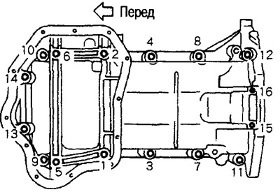
Loosen the set screws in the reverse order of the illustration.
Remove the oil pan with a cutter (special tool).
Installation
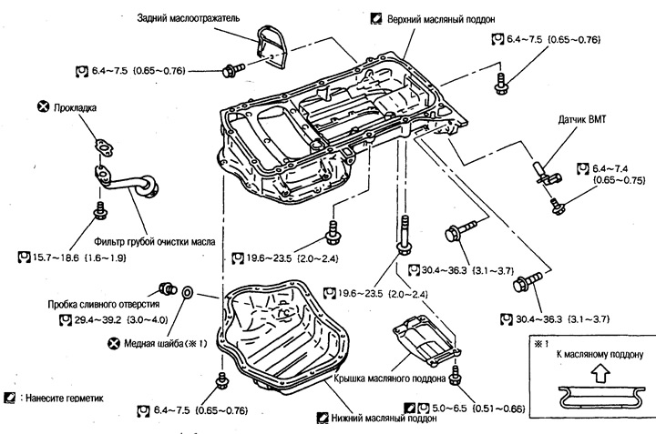
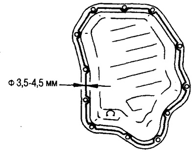
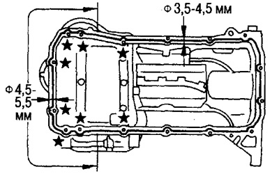
Apply Three Bond 1207C in a continuous bead (KR510 00150) to the places shown in the figure.
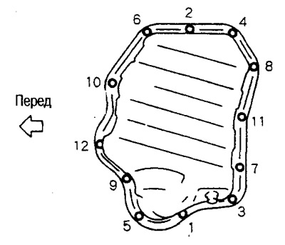 |  |
Tighten the set bolts in the order shown in the figure above.
Removal and installation of the central bearing beam
Removing
Support the gearbox oil pan with a jack.
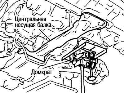
Attention: Support as close to the center as possible.
Lift the engine/gearbox assembly and remove the rear end of the center carrier beam from the gap between the suspension beam and stabilizer bar (4WD models).
Installation
Tighten all set screws (see section «Removing the engine»).
After installation, check the vibration level of the engine mounts (see ch. «Active engine mounts»).
Removal and installation of the upper oil pan
Removing
Loosen the mounting bolts in the reverse order shown in the figure.
Attention: Make sure that bolts no. 15, 16 do not fall into the gearbox.
Remove the upper oil pan with a cutter.
Installation
Apply Three Bond 1207C in a continuous bead (KR510 00150) to the places shown in the figure.
Attention:
In 8 places, marked with asterisks, sealant is applied from the outside of the bolt hole.
The diameter of the sealant strip on the front side is different from the strip of other places.
Tighten the set bolts in the order shown in the figure above.
Mounting bolt lengths vary, so please refer to the bolt dimensions below when installing them.
- М8х25 mm: №№3, 4, 9, 10
- М8х60mm: №№1,2, 5,6, 7, 8,11,12, 13, 14
- MBxZ0mm: No. 15, 16
Note: Bolt lengths do not include heads and guides (the length of the threaded part is indicated).
Removal and installation of the TDC sensor
Removing
Attention:
Be careful not to damage the sensor when removing.
Do not store where there are metal particles.
Do not store in places where there is a magnetic field.
Installation
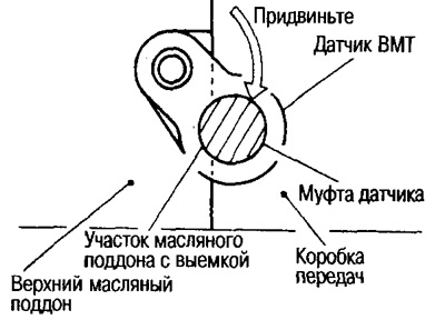
Tighten the set bolt by pushing the TDC sensor sleeve against the recess in the upper oil pan.
Installing the oil pan cover
If the set bolts are reused, remove the old thread sealant, apply Three Bond screw Lock 1303B and tighten.
Note: New bolts are already pre-applied with locking compound, so sealant is not applied.
Installing the A/C Compressor Bracket
Tighten the set bolts to 56.9-65.7 Nm (5.8-6.7 kg m).
Attention: Before carrying out work, disconnect the cable from the negative terminal of the battery.