


Gasoline engine SR20DE cars Nissan Serena 2 (C24)

Spark plug
Examination Check for dirt or damage on the electrodes, for deposits on the insulators. Check the spark gap of all spark plugs. Standard spark gap: 1.0-1.1mm Adjust the...
Examination Check for dirt or damage on the electrodes, for deposits on the insulators. Check the spark gap of all spark plugs. Standard spark gap: 1.0-1.1mm Adjust the...

Air cleaner element
Change interval: every 60,000 km. Compression 1. Warm up the engine to operating temperature and turn it off. 2. Remove the resonator from the valve box cover. 4. Remove...
Change interval: every 60,000 km. Compression 1. Warm up the engine to operating temperature and turn it off. 2. Remove the resonator from the valve box cover. 4. Remove...

Drive belts
Examination The check should be carried out with a cold engine or approximately 30 minutes after stopping it. Visually check for damage on the outer and inner sides of...
Examination The check should be carried out with a cold engine or approximately 30 minutes after stopping it. Visually check for damage on the outer and inner sides of...

Air cleaner and air duct
Removal and installation Preparatory work Disconnect the mass air flow sensor connector. Move the transmission breather hose. Remove the left wing protection (for...
Removal and installation Preparatory work Disconnect the mass air flow sensor connector. Move the transmission breather hose. Remove the left wing protection (for...

Fuel injectors — removal and installation
Preparatory work Relieve fuel pressure. Remove the accelerator cable. Remove the upper intake manifold support. Remove the crankcase ventilation hose (between intake...
Preparatory work Relieve fuel pressure. Remove the accelerator cable. Remove the upper intake manifold support. Remove the crankcase ventilation hose (between intake...

EGR system — removal and installation
Preparatory work Drain the coolant. Remove the air duct and air cleaner housing. Disconnect all wiring and tubing and move to the side. EGR valve 1. Remove the EGR pipe....
Preparatory work Drain the coolant. Remove the air duct and air cleaner housing. Disconnect all wiring and tubing and move to the side. EGR valve 1. Remove the EGR pipe....
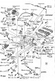
Intake manifold — removal and installation
Preparatory work Relieve fuel pressure. Remove the engine protection from the bottom. Drain the coolant. Remove the front exhaust pipe. Remove the air duct, air cleaner...
Preparatory work Relieve fuel pressure. Remove the engine protection from the bottom. Drain the coolant. Remove the front exhaust pipe. Remove the air duct, air cleaner...

Exhaust manifold — removal and installation
Preparatory work Remove the engine protection from the bottom. Remove the front exhaust pipe. Removal and installation of the oxygen sensor To remove the oxygen sensor,...
Preparatory work Remove the engine protection from the bottom. Remove the front exhaust pipe. Removal and installation of the oxygen sensor To remove the oxygen sensor,...

Exhaust manifold — check
Exhaust Manifold Warping Check Using a ruler and feeler gauge, check for warping of the exhaust manifold contact surface. Limit Warping: 0.3mm
Exhaust Manifold Warping Check Using a ruler and feeler gauge, check for warping of the exhaust manifold contact surface. Limit Warping: 0.3mm

Oil pan and oil prefilter (2WD models) — removal and installation
Preparatory work (mark * indicates work on detaching components from the top side) Drain the engine oil. Remove the engine protection from the bottom. Remove the right...
Preparatory work (mark * indicates work on detaching components from the top side) Drain the engine oil. Remove the engine protection from the bottom. Remove the right...

Oil pan and oil prefilter (4WD models) — removal and installation
Preparatory work (mark * indicates work on detaching components from the top side) Drain the engine oil. Remove the engine protection from the bottom. Remove the right...
Preparatory work (mark * indicates work on detaching components from the top side) Drain the engine oil. Remove the engine protection from the bottom. Remove the right...

Starter — removal and installation
Attention: All work is carried out after disconnecting the cable from the negative terminal of the battery. Removing 1. Remove the air duct. 2. Loosen the fixing bolt at...
Attention: All work is carried out after disconnecting the cable from the negative terminal of the battery. Removing 1. Remove the air duct. 2. Loosen the fixing bolt at...

Valve cover — removal and installation
Preparatory work Remove the high voltage cable bracket. Disconnect high voltage cables. Move aside the engine compartment wiring (located on the front edge of the valve...
Preparatory work Remove the high voltage cable bracket. Disconnect high voltage cables. Move aside the engine compartment wiring (located on the front edge of the valve...

Camshafts — removal
Removing 1. Remove the right engine protection from the bottom and the right mudguard. 2. Remove the valve cover. 3. Set the piston of cylinder No. 1 to TDC in the...
Removing 1. Remove the right engine protection from the bottom and the right mudguard. 2. Remove the valve cover. 3. Set the piston of cylinder No. 1 to TDC in the...

Camshafts — check
Camshaft runout Install the camshaft on a flat surface on two prisms with journals #1 and #5. Install the indicator probe vertically on neck #3. Rotate the camshaft by...
Camshaft runout Install the camshaft on a flat surface on two prisms with journals #1 and #5. Install the indicator probe vertically on neck #3. Rotate the camshaft by...

Camshafts — Installation
1. Install rocker arms, shims, rocker arm guides and valve lifters. Parts are installed in the same places where they stood before removal. Adjusting washers and rocker...
1. Install rocker arms, shims, rocker arm guides and valve lifters. Parts are installed in the same places where they stood before removal. Adjusting washers and rocker...

Camshafts — adjustment
If the camshaft, rocker arms, valves or parts of the valve mechanism have been changed, then select the thickness of the shim depending on the change in the level of the...
If the camshaft, rocker arms, valves or parts of the valve mechanism have been changed, then select the thickness of the shim depending on the change in the level of the...

The chain of the gas distribution mechanism — removal
Removing 1. Remove the engine and transmission assembly from the vehicle. Separate the gearbox from the engine. 2. Install the engine on a special stand (special tool),...
Removing 1. Remove the engine and transmission assembly from the vehicle. Separate the gearbox from the engine. 2. Install the engine on a special stand (special tool),...

Timing chain — installation
1. Install the oil pump drive bush and crankshaft sprocket. Make sure the crankshaft key is pointing straight up (cylinder #1 at TDC). 2. Install the timing chain. When...
1. Install the oil pump drive bush and crankshaft sprocket. Make sure the crankshaft key is pointing straight up (cylinder #1 at TDC). 2. Install the timing chain. When...

Cylinder head — removal
1. Relieve fuel pressure. 2. Remove the engine protection from the bottom. 3. Drain the coolant through the cylinder block and radiator drain holes. 4. Remove the...
1. Relieve fuel pressure. 2. Remove the engine protection from the bottom. 3. Drain the coolant through the cylinder block and radiator drain holes. 4. Remove the...

Cylinder head — installation
1. Apply a continuous bead of Three Bond 1207C Sealant (KR51000150) on the contact surfaces of the cylinder block and front cover. 2. Install the cylinder head gasket....
1. Apply a continuous bead of Three Bond 1207C Sealant (KR51000150) on the contact surfaces of the cylinder block and front cover. 2. Install the cylinder head gasket....

Cylinder head — disassembly
1. Remove the water outlet. Insert the handle of a screwdriver into the water outlet and, by swinging it up and down, remove the nozzle. 2. Using a spark plug wrench,...
1. Remove the water outlet. Insert the handle of a screwdriver into the water outlet and, by swinging it up and down, remove the nozzle. 2. Using a spark plug wrench,...

Cylinder head — check
Warping of the cylinder head 1) Use a scraper to remove carbon deposits, gasket residue, sealant, oil, carbon deposits, etc. from the contact surface of the cylinder...
Warping of the cylinder head 1) Use a scraper to remove carbon deposits, gasket residue, sealant, oil, carbon deposits, etc. from the contact surface of the cylinder...

Cylinder head — assembly
1. If the valve guide was removed, check the clearance before installing it, see above. 2. If the valve seat was removed, check the condition of the contact surface...
1. If the valve guide was removed, check the clearance before installing it, see above. 2. If the valve seat was removed, check the condition of the contact surface...

Removing the engine
Attention: Lift the engine in a safe manner, do not perform unnecessary operations. Do not start work until the exhaust system and engine coolant have cooled...
Attention: Lift the engine in a safe manner, do not perform unnecessary operations. Do not start work until the exhaust system and engine coolant have cooled...

Installing and checking the engine
Installation Installation is carried out in the reverse order of removal, taking into account the following. Do not allow oil to get on the insulators and do not damage...
Installation Installation is carried out in the reverse order of removal, taking into account the following. Do not allow oil to get on the insulators and do not damage...


Cylinder Block — Component Selection Order
*No class division between piston pins and connecting rods (only class 0 exists). Since the markings on a part reflect its original dimensions, do not refer to them if...
*No class division between piston pins and connecting rods (only class 0 exists). Since the markings on a part reflect its original dimensions, do not refer to them if...

Cylinder block — disassembly
1. Remove the engine and transmission assembly from the vehicle. Separate the gearbox from the engine. 2. Install the engine on the stand. a. Remove the exhaust...
1. Remove the engine and transmission assembly from the vehicle. Separate the gearbox from the engine. 2. Install the engine on the stand. a. Remove the exhaust...

Cylinder block — check
Axial play of the crankshaft Use a dial gauge to measure the clearance between the thrust bearing and the crank arm by moving the crankshaft back and forth. Standard...
Axial play of the crankshaft Use a dial gauge to measure the clearance between the thrust bearing and the crank arm by moving the crankshaft back and forth. Standard...

Bending and twisting of the connecting rod
Check with a connecting rod alignment tool. Ultimate bending: 0.15 mm (per 100 mm length) Ultimate torsion: 0.3 mm (per 100 mm length)
Check with a connecting rod alignment tool. Ultimate bending: 0.15 mm (per 100 mm length) Ultimate torsion: 0.3 mm (per 100 mm length)

Large and small connecting rod heads
Big end diameter Install the connecting rod cap without bearing. After tightening the connecting rod bolt to the required torque, use an inside gauge to measure the...
Big end diameter Install the connecting rod cap without bearing. After tightening the connecting rod bolt to the required torque, use an inside gauge to measure the...

How to select connecting rods and piston pins
If a new connecting rod is used Select a connecting rod bearing that matches the journal diameter class of the crankshaft used, according to section «Connecting rod...
If a new connecting rod is used Select a connecting rod bearing that matches the journal diameter class of the crankshaft used, according to section «Connecting rod...

Pistons selection procedure
When a new cylinder block is used: 1) Check cylinder bore class on top of block (1, 2 or 3) and select pistons of the same class. Note: Pistons are installed complete...
When a new cylinder block is used: 1) Check cylinder bore class on top of block (1, 2 or 3) and select pistons of the same class. Note: Pistons are installed complete...

Crankshaft runout
Place the prisms on a flat surface and install the crankshaft on them with the outer journals. Vertically install the indicator on the root neck No. 3. Turning the...
Place the prisms on a flat surface and install the crankshaft on them with the outer journals. Vertically install the indicator on the root neck No. 3. Turning the...

Connecting rod bearing oil clearance
Measurement Install the bearing into the connecting rod and cap, and tighten the connecting rod bolts to the correct torque. Using an inside gauge, measure the inside...
Measurement Install the bearing into the connecting rod and cap, and tighten the connecting rod bolts to the correct torque. Using an inside gauge, measure the inside...

The procedure for selecting connecting rod bearings
When a new crankshaft and connecting rod are used. 1. Find the diameter class of the connecting rod journals from the front or rear side of the crankshaft (0, 1 or 2)...
When a new crankshaft and connecting rod are used. 1. Find the diameter class of the connecting rod journals from the front or rear side of the crankshaft (0, 1 or 2)...

Oil clearance of main bearings
Measurement Install the main bearings in the cylinder block and covers. Measure the inside diameter of the main bearings by tightening the bearing cap bolts to the...
Measurement Install the main bearings in the cylinder block and covers. Measure the inside diameter of the main bearings by tightening the bearing cap bolts to the...

The procedure for selecting main bearings
When a new cylinder block and crankshaft is used 1) The values in the top row of the main bearing selection table correspond to the class of the bearing housing (0, 1, 2...
When a new cylinder block and crankshaft is used 1) The values in the top row of the main bearing selection table correspond to the class of the bearing housing (0, 1, 2...

Cylinder Block — Assembly
1. Blow out the coolant passages, oil passages, crankcase and cylinders with compressed air and remove foreign particles from them. 2. Install the oil jet for the timing...
1. Blow out the coolant passages, oil passages, crankcase and cylinders with compressed air and remove foreign particles from them. 2. Install the oil jet for the timing...

Active Engine Mounts — Description
Active Engine Mount System (further - ACM system) using load sensors determines the vibration of the engine, which is transmitted to the body. With the help of...
Active Engine Mount System (further - ACM system) using load sensors determines the vibration of the engine, which is transmitted to the body. With the help of...


Vibration level adjustment of active engine mounts
Adjust the vibration level after removing or replacing the engine, gearbox, the system itself, the central support beam and its cushions, and also after replacing the...
Adjust the vibration level after removing or replacing the engine, gearbox, the system itself, the central support beam and its cushions, and also after replacing the...


Standard voltage input/output signals of the control unit ACM active engine mounts
Below are the voltage values measured by the tester on the contacts of the ACM control unit and the oscillogram. Measurement data varies based on major factors (mode of...
Below are the voltage values measured by the tester on the contacts of the ACM control unit and the oscillogram. Measurement data varies based on major factors (mode of...

Active engine mounts — checking power and ground circuits
In the event of a malfunction, check the following: Circuits of all contacts of the power supply. Egnition lock. Damage or tight connection of the connectors of the ACM...
In the event of a malfunction, check the following: Circuits of all contacts of the power supply. Egnition lock. Damage or tight connection of the connectors of the ACM...

Active engine mounts — checking input signals
Checking the engine speed signal Start the engine. Check the voltage between terminal 2 of the ACM control unit and «weight». Voltage at idle speed: approx. 4.5V Voltage...
Checking the engine speed signal Start the engine. Check the voltage between terminal 2 of the ACM control unit and «weight». Voltage at idle speed: approx. 4.5V Voltage...

Active engine mounts — check output signals
Checking the output signal of the ACM drive Check the voltage between terminals 18, 19, 22, 25 of the ACM control unit and «weight». Voltage: At idle speed: approx. 11V...
Checking the output signal of the ACM drive Check the voltage between terminals 18, 19, 22, 25 of the ACM control unit and «weight». Voltage: At idle speed: approx. 11V...

Removal and installation of ACM (2WD models)
Removing Description of works Removing the center beam is necessary to remove both the front and rear ACMs. However, if it is not necessary to remove the ACM, leave it...
Removing Description of works Removing the center beam is necessary to remove both the front and rear ACMs. However, if it is not necessary to remove the ACM, leave it...

Removal and installation of ACM (4WD models)
Note: Removal and installation of ACM from the front is carried out in the same way as on 2WD models. The following describes the removal and installation of the ACM...
Note: Removal and installation of ACM from the front is carried out in the same way as on 2WD models. The following describes the removal and installation of the ACM...
This section is available on: russian, bulgarian, belarusian, ukrainian, serbian, croatian, romanian, polish, slovak, hungarian
Similar information for other Nissan models
➜ Power unit: Control system (gasoline) Nissan Almera 1 (1995-2000)
➜ Power unit: Petrol engines 2.0L (MR20) Nissan Qashqai 1 (2006-2013)
Link in different formats to this section
TEXTHTMLBB Code
- General information
- Control devices
- User manual
- Power unit
- Petrol engine SR20DE
- Diesel engine YD25DDTi
- Cooling and lubrication system
- Engine management SR20DE
- Engine management YD25DDTi
- Power and exhaust system
- Transmission
- Automatic gearbox
- Drive and cardan shafts
- Transfer case
- Chassis
- Front suspension
- Rear suspension
- Brake system
- Steering
- Body
- Safety system
- Interior (internal elements)
- Exterior (external elements)
- Doors, locks and windows
- Heating and air conditioning
- Electrical equipment
- Equipment and devices
- Lighting system
- Windshield wipers and washers
- Electrical circuits
NissanBook.ru © 2018–2024 · Mobile version · Articles about Nissan · Sitemap: EN BG BY UA RS HR RO PL SK HU · Feedback · Site search · Bookmark
Almera 1 (N15) · Maxima 4 (A32) · Terrano 1 (petrol) · Patrol 4 (Y60, petrol) · Example 1 (P10, petrol) · Qashqai 1 (J10) · Serena 2 (C24) · Sunny 7 (B13) · Note 1 · Micra 3 (petrol) ·
Almera 1 (N15) · Maxima 4 (A32) · Terrano 1 (petrol) · Patrol 4 (Y60, petrol) · Example 1 (P10, petrol) · Qashqai 1 (J10) · Serena 2 (C24) · Sunny 7 (B13) · Note 1 · Micra 3 (petrol) ·