Preparatory work
(mark * indicates work on detaching components from the top side)
Drain the engine oil.
Remove the engine protection from the bottom.
Remove the right mudguard.
Remove the front exhaust pipe.
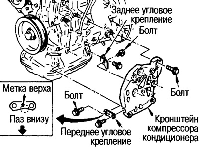
Remove the A/C compressor bracket bracket (see point 5).
Remove the center support beam (see point 2).
Removal and installation of the lower oil pan
Removing
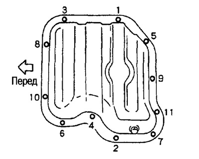
Loosen the mounting bolts in the reverse order of the figure.
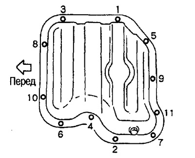
With a cutter (special tool) separate and then remove the oil pan.
Installation
Apply sealant (KR51000150) continuous strip 4.0-5.0 mm wide onto the surface shown in the figure.
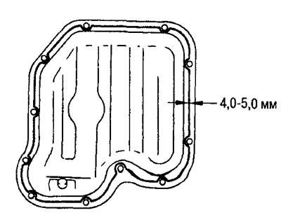
Tighten the set bolts to the correct torque in the order shown in the figure.
Removal and installation of the central bearing beam
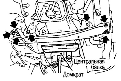
Removing
Place a jack under the gearbox and oil pan.
Attention: If possible, position the jack as close to the center as possible.
Installation
Tighten the fixing bolts to the required torque, see section «Removal and installation of the engine».
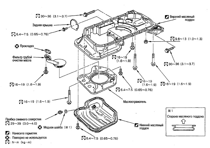
Removal and installation of an oil deflector
Removing
Unscrew only the bolts MB (length 10 mm), M8 bolts (length 12 mm) are unscrewed in the prescribed manner when removing the upper oil pan.
Installation
Apply Three Bond 1303B to the threads of the mounting bolts and tighten to specification.
Removal and installation of the upper oil pan
Removing
Loosen the mounting bolts and nuts in the reverse order of the figure.
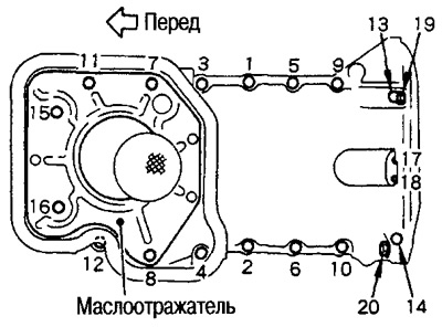
Attention:
- Do not drop nuts 17 and 18 into the gearbox housing.
- Remove the oil pan with a cutter (special tool).
Installation
Apply Three Bond 1207C in a continuous bead (KR51000150), as it shown on the picture.
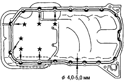
Attention:
- In places indicated in the figure by marks ★, a strip of sealant should go around the outside of the bolt hole.
- If the laying is uneven, fill the gaps with sealant.
Tighten the mounting bolts and nuts in the order shown in the figure.
Tightening torques and bolt sizes vary by location:
- М8х25 mm: №№1,2, 3, 5, 6, 9, 10,12
- М8Х75 mm: №№4, 7, 8, 11, 15, 16 (bolts No. 7, 11, 15, 16 also fasten the oil deflector)
- M8x60 mm: No. 14
- М8Х85 mm: №13
- Nut MB: No. 17, 18
- М10х35 mm: №20 (mount with gearbox)
- M10x45 mm: No. 19 (mount with gearbox)
Removal and installation of angular fastening of an arm of the compressor of the conditioner
Install corner mount front side (label «UP») up.
Press the rear part against the bracket and in this position install on the oil pan.