


Table of contents: Camshaft runout ↓ Camshaft lobe height ↓ Lubricating clearance in the…↓ Camshaft axial play ↓ Visual inspection of the rocker arm ↓ Visual inspection of the hydraulic…↓ Camshaft Sprocket Runout ↓ Valve lifter clearance ↓ Checking for air in the hydraulic…↓
Camshaft runout
Install the camshaft on a flat surface on two prisms with journals No.1 and No.5.
Place the indicator probe vertically on journal No.3.

Turn the camshaft manually in one direction and measure the runout by the deviation of the indicator arrow.
The camshaft runout is equal to half the indicator reading.
- Limit runout: 0.05 mm
Camshaft lobe height
Measure the camshaft lobe height with a micrometer.
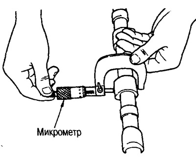
Standard height:
- Intake: 36.787 + 0.095 mm
- Issue: 37.404±0.095 mm
Wear limit:
- Inlet: 0.2mm
- Issue: 0.2 mm
Lubricating clearance in the camshaft journals
Camshaft journal outer diameter
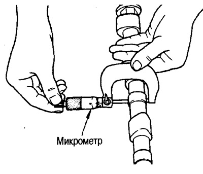
Using a micrometer, measure the outside diameter of the camshaft journal.
- Standard diameter: 27.935-27.955 mm
Inner diameter of camshaft bracket
Tighten the camshaft bracket bolts to the specified torque.
Measure the inside diameter of the camshaft bracket with a bore gauge.
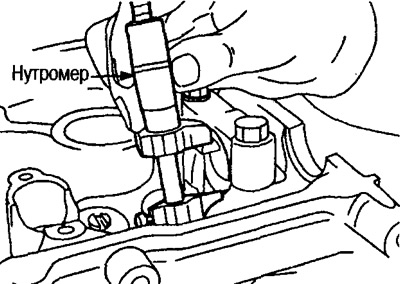
- Standard diameter: 28.000 - 28.021 mm
Calculation of lubrication gap in camshaft journals
(Lubrication gap) = (Inner diameter of camshaft bracket) - (Camshaft journal outer diameter)
- Standard clearance: 0.045-0.086 mm
- Limit clearance: 0.15 mm
If the camshaft journal lubrication clearance exceeds the specification, recheck the camshaft bracket ID, camshaft journal OD, and replace the cylinder head assembly, camshaft, or both as necessary.
Note: The camshaft brackets are manufactured as one piece with the cylinder head and therefore cannot be replaced individually.
Camshaft axial play
Set the indicator in the direction of the stop against the front end of the camshaft. Measure the axial clearance by moving the camshaft back and forth in the axial direction.
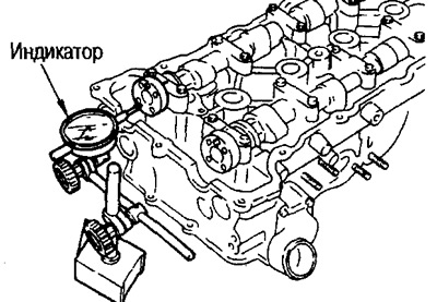
- Standard clearance: 0.055-0.139 mm
If the clearance exceeds the nominal value, replace the camshaft and measure again. If the reading is still different from the norm, replace the cylinder head.
Visual inspection of the rocker arm
Check for wear in the area of the pivot axis, the contact surface of the camshaft cam lobe and the valve.
Make sure the bearing rotates freely.
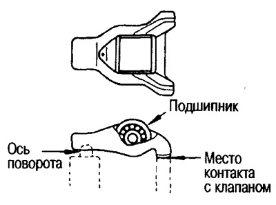
Visual inspection of the hydraulic valve lifter
Make sure that there is no damage or wear on the rubbing parts of the rocker arm and on the surface of the cylinder head.
Camshaft Sprocket Runout
This check is performed after measuring the axial clearance of the camshaft. Tighten the camshaft sprocket to the required torque.
Using an indicator, measure the runout of the camshaft sprocket.
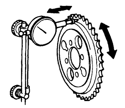
- Limit runout: 0.25 mm
Valve lifter clearance
Valve lifter outer diameter
Using a micrometer, measure the outside diameter of the hydraulic lifter.
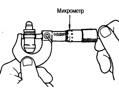
- Standard diameter: 16.980 - 16.993 mm
Valve lifter hole diameter
Using a bore gauge, measure the diameter of the hole for the hydraulic valve lifter in the cylinder head.
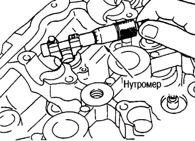
- Standard diameter: 17,000- 17,020 mm
Calculation of valve lifter clearance
(Hydraulic tappet clearance) = (Diameter of the hole for the hydraulic tappet) - (Outside diameter of hydraulic tappet)
- Standard clearance: 0.007 - 0.040 mm
- Limit clearance: 0.073 mm
If the obtained values differ from the nominal values for the inside and outside diameters, replace the valve lifters or the cylinder head, or both.
Checking for air in the hydraulic tappet
After installing a new hydraulic valve lifter, and also if extraneous sounds are heard while the engine is running, check if there is air inside the hydraulic lifter.
Press the rocker arm firmly and measure its movement. If the movement is more than 1 mm, perform the operations to remove air from the hydraulic tappets using the method described below.
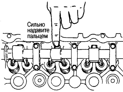
1. Remove the hydraulic valve lifter, place it in engine oil and, pressing on the plunger with your fingers, lightly press on the locking ball with a thin rod.
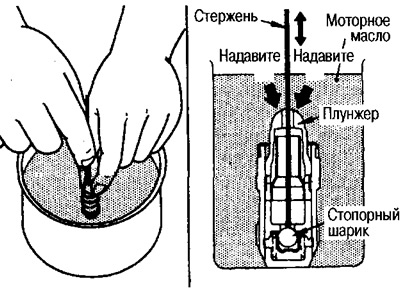
2. If the plunger stops moving, the air has escaped.
3. If air cannot be released, replace the hydraulic valve lifter.
Attention:
Be careful not to damage the locking ball.
Do not disassemble the hydraulic valve lifter.