Warping of the cylinder head
1) Use a scraper to remove carbon deposits, gasket residue, sealant, oil, carbon deposits, etc. from the contact surface of the cylinder head.
Caution: Do not allow gasket residue, sealant, or other foreign matter to enter oil or water passages.
2) Check the underside of the cylinder head for warpage in six directions.
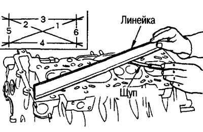
- Limit Warping: 0.1mm
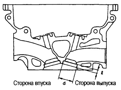
Valve sizes
Use a micrometer to check the dimensions of the valves.
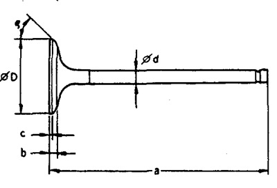
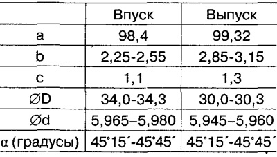
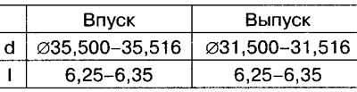
Standard valve sizes (mm):
Valve guide clearance
Make this check before removing the valve guide.
Make sure the valve stem diameter is within specification (see above).
Press the valve about 10 mm towards the combustion chamber, rock the valve in different directions and use the indicator to measure the amount of movement.
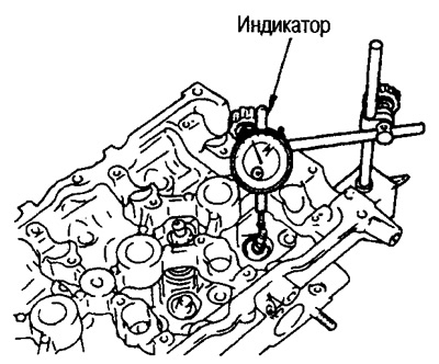
The valve guide clearance is ½ of the indicator reading.
Standard Clearance:
- Inlet: 0.020 - 0.053 mm
- Outlet: 0.040 - 0.073 mm
Limit clearance:
- Inlet: 0.08mm
- Outlet: 0.1mm
Valve Guide Replacement
When replacing a valve guide, replace it with a larger valve guide (by 0.2 mm) repair size.
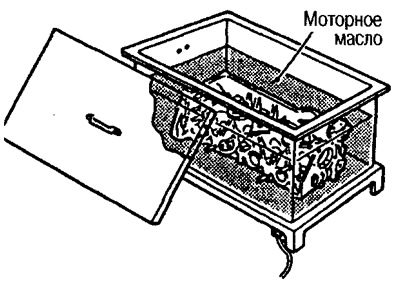
1) Heat the cylinder head to 110-130'C by placing it in a container of engine oil.
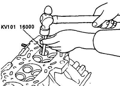
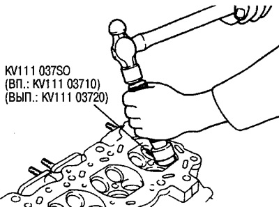
2) Knock out the valve guide from the combustion chamber side with a hammer and punch (special tool).
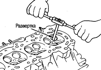
3) Using a reamer, finish the surface of the hole for the valve guide.
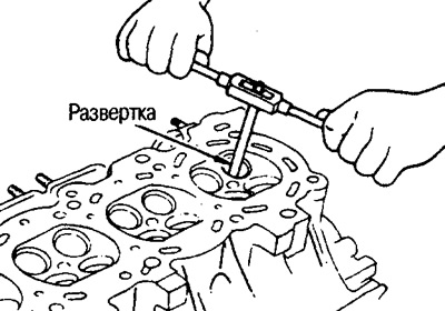
- Standard reamed hole diameter: 10.175-10.196mm
4) Heat the cylinder head to 110-130°C by placing it in a container of engine oil.
5) Using a press, press in the valve guide or tap in with a hammer and drift (special tool) from the distributor side.
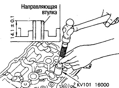
- Special tool diameter: 6 mm
The installation dimension of the valve guide is shown in the figure on the previous page.
6) Ream the installed valve guide.
- Final standard diameter: 6.000-6.018 mm
Valve seat contact pattern
Perform this check to ensure that the valve guides and valves themselves are the correct size.
Apply red lead to the contact surface of the seat and valve and check that the valve is evenly seated.
Make sure that the ink imprint shows up around the entire circumference without breaks.
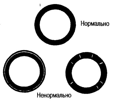
Otherwise, lap the valve and recheck. If the contact surface is still abnormal, replace the valve seat.
Valve seat replacement
If the valve seat is removed, replace it with an oversized seat (by 0.5 mm) repair size.
1) Drill out the old saddle until it breaks. Drilling must not continue deeper than the bottom of the seat recess in the cylinder head. For this purpose, put a drilling depth gauge on the drill.
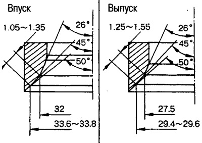
2) Ream out the oversize valve seat recess in the cylinder head.
standard enlarged (by 0.5) dimensions (mm)
Ream in concentric circles towards the center of the valve guide. This will ensure proper seating of the valve seat.
3) Heat up the cylinder head to approx. up to 110-130°C by placing it in a container with engine oil.
4) Cool the valve seat with dry ice. Press the valve seat into the cylinder head using a drift (special tool).
Caution: Do not touch chilled saddles with bare hands.
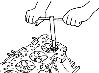
5) Bring the saddle to the required dimensions by milling.
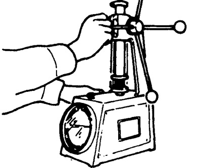
Attention:
When processing a surface with a cutter, grasp the handle of the tool with both hands. Then press the cutter against the contact surface around the entire circumference and mill in single passes. If the tool is pressed incorrectly, the valve seat may take on a stepped shape.
Process until the dimensions shown in the figure are obtained.
6) Lappe the valve with grinding paste.
7) Recheck the condition of the valve seat.
Valve spring irregularity
Attach the angle to the valve spring and turn it. Measure the maximum clearance between the spring and the angle.
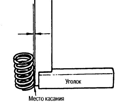
- Ultimate non-rectangularity: 2.1 mm
Valve spring dimensions and compression pressure
Measurements are taken with a special valve spring tester.
 |  |