Note. Severe overheating of the engine can lead to deformation of the cylinder head and violation of the flatness of its mating surfaces.
Cleaning
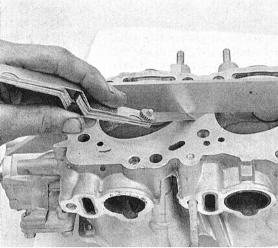
1. Scrape off all traces of the old gasket material and sealant from the mating surfaces of the cylinder head, intake manifold and exhaust manifold, - try not to damage the surfaces. The use of a special softener, which should be pre-soaked with adhering deposits, will greatly facilitate the work - ask in car accessories stores.
2. Remove all traces of scale from the walls of the water channels.
3. Thoroughly clean all accessible cavities and openings with a stiff wire brush. In case of severe contamination of the channels, head cleaning should be entrusted to specialists.
4. "Drive away" with a suitable tap for each of the bolt holes, removing corrosion products from the thread, traces of old sealant and restoring damaged turns. If you have access to a compressed air source, blow out the holes to remove chips and small debris.
Attention! Remember to wear protective goggles when using compressed air!
5. Use solvent and a brass wire brush to clean the combustion chambers of carbon deposits.
6. Wash the head with solvent and dry thoroughly. The use of compressed air will significantly reduce the drying time and will guarantee the quality of cleaning hard-to-reach cavities and holes.
Note. Various kinds of compositions for removing traces of soot, which greatly facilitate the cleaning procedure, can be purchased at many car accessories stores. Remember that these types of products are usually chemically aggressive and must be used with appropriate precautions - strictly follow the manufacturer's instructions, usually given on the container label.
7. On SOHC engines, clean the rocker arm assemblies with axles in solvent. Dry the components thoroughly with compressed air and fold them in an organized manner. Clean with solvent and dry the valve lifters.
Note. The use of compressed air will greatly facilitate the procedure (don't forget to wear safety glasses).
8. Wash in solvent and thoroughly dry the valve springs, their plates and crackers of split locks. Try not to mix up the components.
9. Scrape off the bulk of deposits formed on the surfaces of the valves, then with a wire nozzle to an electric drill, finally clean the surfaces of the valve stems and plates - make sure that the valves are not mixed up.
Status check
Note. Carefully examine the condition of the cylinder head before deciding whether to remake the cylinder head. After reviewing the material presented in this subsection, make a list of components that need special attention.
Cylinder head
1. Carefully check the cylinder head for signs of coolant leaks, cracks or other damage. A cracked head must be replaced without fail. If there is no certainty in determining the condition of the head, it should be sent for verification to a car service workshop. If repair is not possible, replace the defective head.
2. Using a flatness gauge and a blade-type feeler gauge, check the head mating surface for signs of deformation. If the flatness exceeds the value allowed by the standards (see specs), the head must be sent to the groove in the mechanical workshop.
Note. One of the operating parameters of cylinder heads is their minimum allowable height, which must not be reduced during machining.
3. Check the condition of the valve seats in each of the combustion chambers. In case of revealing cavities, cracks, traces of burnout, the head should be subjected to a special restorative repair, the implementation of which lies beyond the qualifications of an average amateur mechanic and should be entrusted to car service specialists.
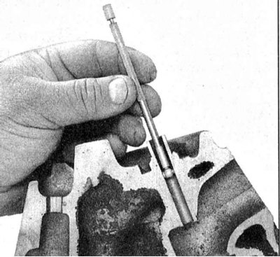
4. Using a bore gauge, measure the inside diameter of the valve guide. After removing the gauge from the sleeve, it is measured with a micrometer. Also measure the outer diameter of the valve stem. Subtract the second measurement from the first measurement to determine the valve seat gap. Compare the received data with the requirements of the Specifications. Worn bushings must be replaced.
Note. when using an inside gauge, insert it to the middle of the sleeve length, then move it up and down. Uneven resistance to movement of the meter indicates the presence of a taper bushing. If you are unsure when determining the condition of the components, do not hesitate to seek help from specialists.
Valves
1. Carefully check the valve surfaces for signs of uneven wear, deformations, cracks, cavities and burn marks. Assess the degree of actuation of the valve stems. Check for cracks in the necks of the rods. Check the valves for bending by rotating them. Check for cavities and signs of excessive end wear. Identification of any of the listed defects requires the delivery of valves for refurbishment to a car service workshop.
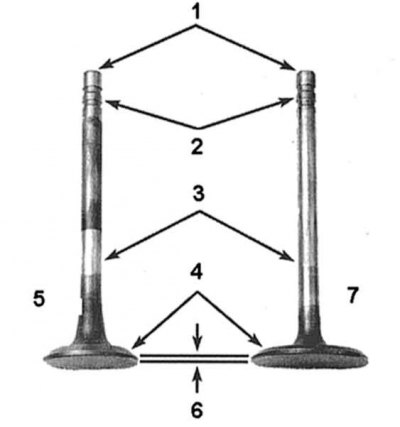
1 - Ends (liners) rods; 2 - Grooves for the installation of crackers for split locks of plates; 3 - Rods; 4 - Working chamfers; 5 - Exhaust valve; 6 - Cylindrical part of the plate (belt); 7 - Inlet valve
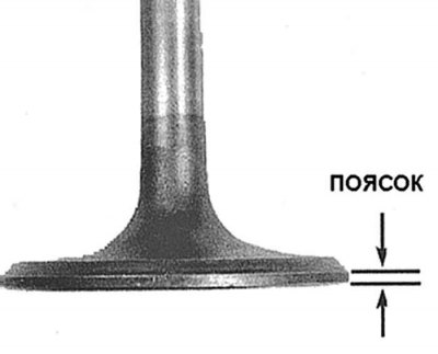
2. Measure the width of the cylindrical part (girdle) plates of each of the valves. If the belt width is less than the value specified in the Specifications, replace the valve.
Valve components
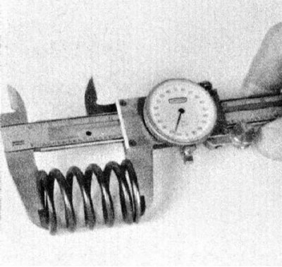
1. Assess the degree of wear of the end parts of each of the valve springs, check the springs for cavities. Measure the free length of the valve springs, compare the results of measurements with the requirements of the Specifications. If the spring is shorter than the lower limit, it is sagging and must be replaced. Also check the forces developed by the springs for compliance with regulatory requirements (it is better to entrust this work to the specialists of the car service workshop). In the absence of confidence in determining the condition of the springs, it would be more correct to replace them.
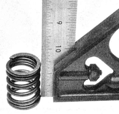
2. Installing each of the springs vertically on a flat surface, check the severity of their facing. Springs with violation of trimming, as well as sagging (see above), are to be replaced.
3. Check the spring plates and crackers of their split locks for cracks and signs of wear. All parts in doubtful condition should be replaced with new ones to avoid the development of defects in the future.
Camshafts, valve lifters and rocker arm assemblies with axles
1. A description of the procedures for checking the status of the listed components is given in Section Checking the condition of camshafts, valve lifters and bearings. An assessment of the condition of the bearing journals of the camshafts must be made before the head is sent to a workshop for valve service. The presence of scratches, scoring and other mechanical defects on the necks of the head must be replaced regardless of the condition of the components of the valve mechanism. When servicing the SOHC engine, the condition of the valve rocker arms with axles should also be checked.
2. Replace any defective components found.
3. With a significant degree of wear of the valve components, which is quite likely for an engine in need of major repairs, assemble the valve assemblies, install them in their regular places in the head (see Section Cylinder head assembly) and proceed with valve maintenance procedures (see Section Valve maintenance).