


Note: Removal of the crankshaft is only possible with the engine removed from the vehicle. This assumes that the flywheel/drive plate, crankshaft pulley, timing belt/chains with gears/sprockets, oil pan, oil pickup, oil pump and connecting rod and piston assemblies have already been removed (see Part SOHC engines or DOHC engines of this Chapter). Before removing the crankshaft, it is also necessary to unbolt and separate the rear oil seal holder from the cylinder block.
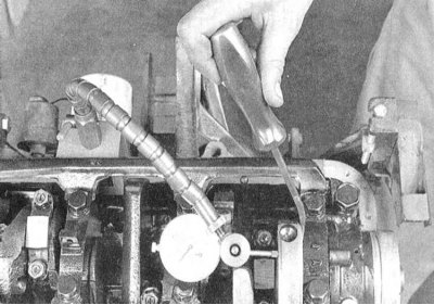
1. Before removing the crankshaft from the engine, measure its axial play. Attach the DTI gauge to the block coaxially with the crankshaft, resting its plunger against the cheek of one of the crankpins or against the end of the shaft journal.
2. Push the crankshaft back as far as it will go and reset the gauge indicator. Now push the shaft in the opposite direction and read the gauge reading. The amount of free play of the shaft in the longitudinal direction is its axial play. Compare the measurement result with the requirements of the Specifications. If the play exceeds the maximum permissible value, check the thrust surfaces of the shaft for signs of excessive wear. If there are no obvious signs of wear, installing new thrust washers will usually help correct the situation.
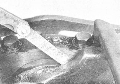
3. If you don't have a dial gauge at hand, you can use a regular blade-type feeler gauge. Carefully move the shaft forward along the engine until it stops, then determine the size of the resulting gap between the crank cheek and the front wall of the rear (thrust) main bearing by tightly fitting a feeler gauge blade(s) of the appropriate thickness into it.
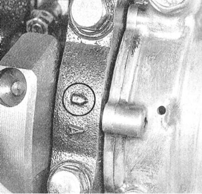
4. In several stages (1/4 turn per set) in a strictly defined order, the reverse order of their tightening (see section Installing the crankshaft and checking the main bearing clearances), loosen the main bearing cap mounting bolts enough to be able to unscrew them by hand. The main bearing caps are usually equipped with cast marks in the form of arrows, which point towards the timing drive when installed correctly. If necessary, apply such markings yourself using a center punch.
Note: On SOHC engines, it is sufficient to mark the direction of fit of the front and rear bearing caps only - the other caps are a monolithic assembly.
5. Carefully tap the bearing caps with a soft-faced hammer and remove them from the engine block. If necessary, use the bolts as levers. Make sure that the main bearing shells inserted in the caps are not lost when dismantling them.
6. Carefully remove the crankshaft from the engine (due to the significant weight of the assembly, it would be wise to enlist the help of an assistant). Make sure the main bearing shells remain in their beds in the block and caps. Install the caps in their regular places on the block, and hand tighten the mounting bolts.
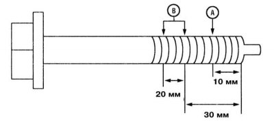
7. On DOHC engines, it is necessary to assess the degree of stretching of the main bearing cap bolts. If the difference between the diameters of the threaded part of the bolt measured in the areas marked in the illustration exceeds 0.11 mm, the bolt must be replaced.
Note: Strictly speaking, it makes sense to immediately purchase a replacement set of mounting bolts and use them during assembly.