


Table of contents: Checking the working clearances of…↓ Final installation of the crankshaft ↓
1. Installing the crankshaft is the first step in the actual engine assembly procedure. It is assumed that at this stage the crankshaft and engine block have already been properly cleaned, inspected and subjected to the necessary refurbishment.
2. Turn the engine upside down.
3. Loosen the mounting bolts, remove the main bearing caps and lay them out on the workbench in the order of installation on the engine.
4. If you haven't already done so, remove the old main bearing shells from their beds in the block and caps. Wipe the beds with a clean, lint-free cloth - they should be spotlessly clean.
Checking the working clearances of the main bearings
Note: Try not to touch the surfaces of new bearings with bare hands to avoid unwanted contact of bearings with traces of oil and chemically aggressive substances that are always present on fingers.
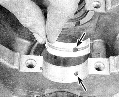
1. Wipe the backs of the new main bearing shells and insert the halves equipped with an oil groove into their beds in the block. Insert the remaining halves of the shells into the corresponding bearing caps. Make sure that the tongues of the shells enter the corresponding mounting grooves in the beds of the block and caps. The oil holes in the block must be correctly aligned with the holes in the shells.
Note: Do not attempt to hammer a stubborn bearing into your bed under any circumstances. Do not lubricate the bearings at this stage!
2. On SOHC engines, flanged thrust bearings are installed in the cover and seat of the 4th main bearing. On DOHC engines, the third bearing is the thrust bearing.
3. Wipe the bearing surfaces in the block and the crankshaft main journals with a clean, lint-free cloth.
4. Check the patency of the shaft oil holes, clean them if necessary. Any foreign particles contained in the oil flows will eventually inevitably end up in the bearings.
5. Carefully place the thoroughly cleaned crankshaft into the main bearings of the block (do not use any lubricant).
6. Before finally installing the shaft, it is necessary to check the working clearances in its main bearings.
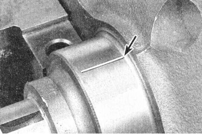
7. Cut the calibrated plastic wire from the Plastigage measuring kit into pieces slightly shorter than the width of the bearing shells and place one piece of wire along each of the main journals of the shaft, parallel to their axis.
8. Wipe the surfaces of the liners in the covers and install the latter in their regular places (make sure the markings are oriented correctly). Try not to move the calibrated wire sections laid along the shaft journals. Lightly lubricate the threads of the mounting bolts with oil and screw them in, securing the covers.
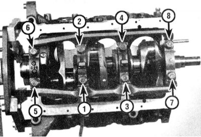
9. Tighten the cover mounting bolts in three stages in the order shown in one of the illustrations to the required force. Do not allow the shaft to turn while tightening the fasteners!
Caution! The condition of the main bearing cap mounting bolts must be carefully checked beforehand (see section Removal the crankshaft) to avoid discrepancies between the torque wrench readings and the actual tightening force.
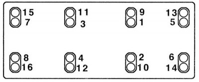
10. Remove the bolts and carefully remove the main bearing caps. Stack the removed caps in the order they are located on the engine. Try not to damage the flattened calibrated wire and do not turn the shaft. If any of the caps cannot be removed, gently tap them with a soft-faced hammer to release them.
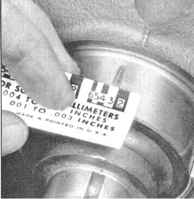
11. Using the width of the flattened threads measured on the scale printed on the Plastigage kit packaging, determine the size of the bearing operating clearances. Compare the measurement results with the requirements of the Specifications.
12. If the clearance value is outside the permissible limits, it is possible that the wrong size bearings were installed (see section Checking the condition and selecting the liners of the main and connecting rod bearings of the crankshaft). Before looking for new inserts, make sure that no dirt or oil has gotten under the inserts at this stage. If the calibrated wire is flattened more at one end than the other, this indicates the presence of a taper in the neck (see section Checking the condition of the crankshaft).
13. Carefully remove the flattened calibrated wire from the necks, scraping off all traces of it with some not very strong tool (for example, the edge of an old credit card). In extreme cases, you can use your own fingernail - the main thing is that there are no scratches or burrs left on the surface of the necks/liners.
Final installation of the crankshaft
1. Carefully remove the crankshaft from the engine.
2. Wipe the bearing surfaces in the block and evenly lubricate them with a thin layer of molybdenum-containing or assembly engine grease. Do not forget to lubricate the thrust surfaces as well.
Caution! Try not to let grease get on the backs of the liners!
3. Make sure the crankshaft journals are absolutely clean, then lubricate (the same lubricant or clean engine oil) surfaces of the journals that contact the seals. Place the shaft in its regular place.
4. Wipe and lubricate the bearing cap liners.
5. Install the bearing caps on the engine (arrows pointing towards the timing belt drive).
6. Screw in the mounting bolts and tighten them to 14÷16 Nm.
7. Tap the ends of the shaft journals with a hammer through a brass or lead drift to align the thrust surfaces and seat the shaft before finally tightening the fasteners.
8. Tighten the cover bolts to the required torque.
9. Turn the crankshaft by hand several times, checking for freedom of rotation.
10. Finally, use a blade type feeler gauge or DTI gauge to determine the amount of shaft end play (see section Removal the crankshaft). If the thrust surfaces of the shaft are not worn or damaged, and the bearings are replaced with new ones, the amount of play should not exceed the permissible range.
11. Install the new rear crankshaft oil seal and bolt its holder to the block (see section Installing the rear crankshaft oil seal).