


Valve clearances on all engines are adjusted when warm, but the engine should not be running. To set the engine to the required operating valve clearances after repair, Specifications the values given are for a cold condition. However, the clearances of all valves should also be checked after the engine has cooled down. If it is necessary to adjust the valve clearances, preparatory work must be carried out, i.e., removing the cylinder head cover, unscrewing the spark plugs, etc.
The valve clearance is measured between the end of the tappet and the camshaft lobe. Adjustment is made as follows:
1. Turn the crankshaft (if the spark plugs are removed, this can be done using the V-belt), until the mark on the belt pulley coincides with the TDC mark on the ignition adjustment plate. The piston of the 1st cylinder will be in the TDC position (see illustration below). If you now slowly turn the shaft from side to side, you can notice that the pusher of the first or fourth cylinder moves up and down, i.e. the valves overlap. If this happens with the valves of the 4th cylinder, the piston of the 1st cylinder is in the TDC position; otherwise, turn the crankshaft half a turn.
2. Measure the valves of cylinder 1 and all valves shown in the illustration and record the clearance of each valve.
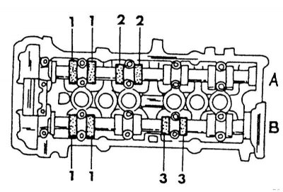
Measuring the valves of the intake camshaft (A) and exhaust camshaft (B) when the piston of the 1st cylinder is in the TDC position.
3. To check the clearance, insert a flat feeler gauge between the tappet surface and the cam as shown in the illustration below. A sign of a correctly adjusted clearance is that the feeler gauge is pulled in with difficulty at first, then more easily.
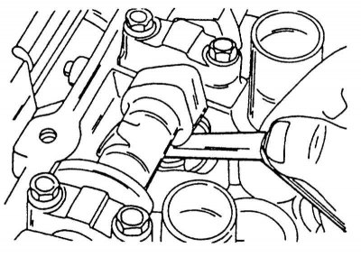
Checking the valve clearance with a flat feeler gauge at the specified location.
4. Turn the crankshaft half a turn so that the piston of the 4th cylinder is in the TDC position. Check that the noses of both cams of the fourth cylinder are facing up and check the valves (illustration below) in the manner described above.
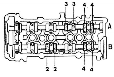
Measuring valve clearances when the piston of the 4th cylinder is at TDC.
(Data taken from this portal: NissanBook.ru)
5. If the valve clearances are within the permissible limits, you can install the removed parts. Otherwise, you should adjust the corresponding clearance. It should be noted that two special devices are used to replace the adjusting washers in Nissan workshops. In any case, there must be a strong magnetic rod. The tappet of the adjustable valve must be pressed inward to remove the washer with the help of a magnet.
6. Turn the crankshaft so that the cam nose of the adjustable valve is facing upward.
7. Using a small screwdriver, turn the tappet so that the notch on the edge points toward the center of the cylinder head.
8. Now press the plunger inwards with a special tool or screwdriver and with a small screwdriver move the washer to the side so that it can be removed with a magnetic rod. An assistant should hold the plunger pressed in.
9. Use a micrometer to measure the thickness of the washer. Although the washer has a designation (TS 224 means washer thickness is 2.24 mm), the washer must be measured, as it may be worn. From the obtained value, the thickness of the required washer can be determined using the following formula:
- 10. N= R +(M-0.37) — intake valves
- 11. N= R +(M-0.40) — exhaust valves
- "N" is the thickness of the new washer, "R" is the thickness of the old washer and "M" is the value of the measured valve clearance.
10. There are 50 thickness values of adjusting washers from 2.00 to 2.98 mm in 0.02 mm increments. From this list, select the washer with the closest thickness value to the obtained value. The thickness designation should be at the bottom after installation. When installing the washer, press the pusher inward again and install the washer in place using a magnet and a small screwdriver.
11. Check all adjusted valve clearances again after installing new washers. As already mentioned, the clearance should be checked on a warm engine.
12. Install all removed parts. Do not make a mistake when connecting the ignition cables, otherwise the engine will not start.