Idle speed is adjusted at the factory and no further adjustment is required.
Only if the CO content after long-term operation ceases to meet the standards, the carburetor should be adjusted.
Carburetor
Before checking and adjusting, the following parts must be in perfect condition:
1. With servo control installed, center the front wheels. The handbrake should be applied.
- The battery must be charged.
- Engine oil and coolant levels must be at the correct level.
- All vacuum hoses must be connected.
- The air intake system must be sealed.
- Cylinders must have good compression.
- The exhaust gas return system must work flawlessly.
- The throttle valve should open and close well.
- Switch off all electrical consumers, such as headlights, heater fan, rear window defroster, etc.
- The cooling fan should not run.
2. Warm up the engine, i.e. the needle of the remote thermometer should be in the middle position. During adjustment, the engine must maintain its operating temperature, i.e., the engine must be started during pauses in order to warm it up again. The engine must be running at less than 1000 rpm.
3. Connect the tachometer according to the instruction manual.
4. Start the engine and look through the carburetor sight glass to check that the fuel level is in the center line.
5. Accelerate the engine for two or three minutes to 2000 - 3000 rpm and then let it idle for one minute.
6. Remove the idle speed on the tachometer. The engine must run at 750±50 rpm.
7. If the idle speed does not match the required value, turn the screw until the value is within the required limits. If the idle speed cannot be adjusted and all of the above systems are in good condition, the carburetor may need to be replaced.
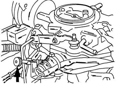
The knurled screw is used to adjust the carburetor.
8. Stop the engine. The tachometer remains connected.
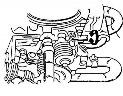
9. In the middle of the exhaust manifold cover, disconnect the lambda probe plug. The second plug must be disconnected from the intake air control valve. It is in the position shown in the illustration on the right side of the ignition coil in front of the suspension strut (if you stand in front of the engine compartment).
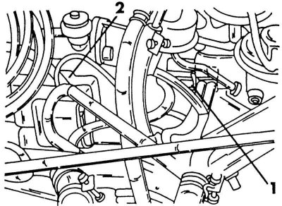
Intake air control valve position (1) next to the ignition coil (2).
10. On the right, next to the heat shield of the exhaust manifold, you can see the intake tube for measuring the CO content. Remove the tubing cap and connect the CO meter as instructed. The connection between the measuring device and the tube must be tight.
11. Start the engine, accelerate it to 2000 - 3000 rpm and then return to idle. Read the instrument readings. The value must be within 1.0±0.5%. If the CO content does not correspond to the required value, turn the adjusting screw inserted into the throttle valve block. It is sealed to prevent unauthorized rotation. Since the carburetor must be removed, among other things, and in order to drill out the seal, this work is recommended to be carried out by a specialized workshop. The illustration shows the location of the seal. If the work is done independently, you can not drill the seal too deep. After drilling out the seal, reinstall the carburetor and turn the screw inside with a regular screwdriver until the CO value is within the required limits. After adjustment, check the idle speed again and finally insert a new seal into the hole. The carburetor does not need to be removed for this.
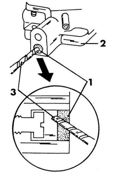
Seal (1) for CO adjusting screw in throttle body (2) can be drilled in the specified way with a drill (3).
Vehicles without a catalyst
Idling is adjustable, just like on models with a catalyst, however, to adjust the composition of the mixture, a special screwdriver is needed, which is inserted into the serifs of the adjusting screw (see illustration below), tachometer and, for best results, a CO meter. If necessary, work can be carried out without the last device, if the instructions are strictly followed, but be aware of environmental laws.
1. First, adjust the idle speed.
2. Perform the preparatory operations already described and take the tachometer readings. If the idle speed is outside 750±50 rpm, the idle speed must be adjusted. The idle speed adjusting screw looks the same as shown in illustrations. Check the CO content with a suitable instrument and adjust if necessary.
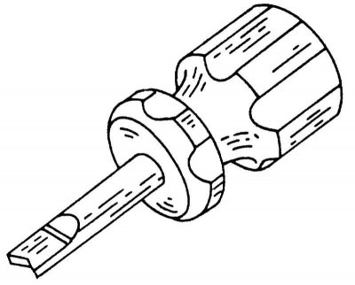
A special screwdriver for adjusting the mixture at idle.
Without CO content meter
1. Check that the engine is at its operating temperature.
2. To adjust the composition of the mixture, there is a screw under the idle adjustment screw. Fully screw in this screw using a special screwdriver (not too hard) and back out two full turns. The idle speed should then increase by 50 rpm, compared to the already existing value.
3. Using a special screwdriver, turn the mixture adjustment screw so that the engine runs at the highest possible speed. After that, screw in the idle speed screw until the engine runs with the appropriate Specifications the number of turns. The content of CO should more or less correspond to the required value, i.e., it should lie within 1.5±0.5%.
With a CO meter
1. Adjust idling as already described.
2. Check that the engine is still at its operating temperature.
3. Connect the CO meter. The hose must be pushed into the exhaust pipe at least 40 cm.
4. Check through the carburetor sight glass that the fuel level is in the center line.
5. Using a special screwdriver, turn the mixture adjustment screw so that the device shows a value of 1.5±0.5%.
6. Repeat the described adjustments until the CO content and RPM are correct.
Multi-position injection system
Idle speed and CO content are usually adjusted automatically by the control device, however, it may be necessary to carry out an adjustment if, after a long operation, the idling speed does not meet the requirements. It is best to go to a Nissan workshop, but if you follow the following description carefully, you can adjust the idle speed yourself.
Before checking and adjusting, the following conditions must be met, i.e. the elements and systems listed below must be in perfect condition.
1. Set the front wheels to the middle position, tighten the handbrake.
2. The battery must be well charged.
3. The ignition system must be in good condition and work flawlessly.
4. The level of impellent oil and coolant must correspond to the required values.
5. All vacuum hoses must be connected.
6. The air intake system must be sealed.
7. The compression of the cylinders must correspond to the required values.
8. Throttle should open and close fully.
9. All fuses must be inserted.
10. Turn off all electrical consumers, i.e., for example, headlights, heater fan, rear window defroster, etc.
11. When measuring the CO content, insert the measuring tube of the device into the exhaust at least 40 cm.
12. On the automatic transmission, set the lever to the position «N».
13. Turn off the air conditioner.
14. The cooling fan should not work.
15. When checking idling, proceed as follows:
16. Warm up the engine, i.e. the needle of the remote thermometer should be in the middle position. When adjusting, the engine must be at operating temperature, i.e., restart the engine during pauses and warm it up. The engine must be running at less than 1000 rpm.
17. Stop the engine and connect the tachometer according to the instructions.
18. With the engine off, locate the throttle position sensor (see illustration) and unplug. Start the engine.
19. Accelerate the engine for 2 or 3 minutes to 2000 - 3000 rpm and then let it idle for two minutes.
20. Take readings from the tachometer. The engine must be running at 800 rpm.
21. If the idle speed does not match the required value, turn the screw (1) (see illustration below), until the number of revolutions reaches the required value. Turning to the left decreases the speed, turning to the right increases it. If the idle speed value cannot be determined, and all the above systems and components are in good condition, contact a Nissan workshop.
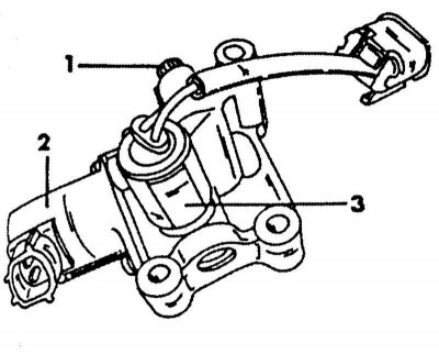
View of auxiliary air valve and related components
1 - adjustment bolt XX; 2 - additional air valve; 3 - switching valve
22. Stop the engine. The tachometer remains connected.
23. Stop the engine, connect the throttle position sensor plug and start the engine again.
24. Accelerate the engine 2-3 times to 2000 rpm and read the idle speed on the tachometer. The number of revolutions must lie within the limits of 850±50 rpm. Unsatisfactory idling may be due to the secondary air valve, its cables, or the electronic control unit.
25. Measure the CO content in accordance with the instructions for the measuring device. If the value is not equal to 0.5%, you need to find the reason for this in the workshop. Accurate measurement and adjustment of the CO content is associated with some difficulties and therefore is not described.
Central injection system
Idle screw position (1) on the SR20Di engine.
The injection system adjusts idle speed automatically to a predetermined value.
Idle speed is controlled by finely adjusting the amount of air that bypasses the throttle through the secondary air valve. The auxiliary air valve turns on and off to precisely control the amount of air. The crank angle sensor monitors the exact number of engine revolutions and reports the information to the control unit. Based on the received data, the control device turns on or off the auxiliary air valve in order to maintain the idle speed at a pre-programmed value. Other factors such as engine warm-up, coasting, fuel consumption and engine load (air conditioning, electrical load) are automatically assessed and compensated.
Although not normally required, the idle can be checked and adjusted. Before checking and adjusting, the requirements given for the multi-position injection system must be met. The idle check is carried out in the same way as described above for the carburetor. Cars with manual and automatic transmissions have the same idle speed.
Air filter
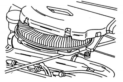
Removing and installing the air filter element. Left for SR20DE engine, right for SR20Di engine.
The air filter has a paper element that cannot be cleaned. The filter element must be replaced every two years or every 60,000 km. To remove the element, remove the cover and remove the old element. On fig. above shows the removal of the filter element on both engines. Collected dust should be removed from the filter housing with a cloth. Insert a new filter element and replace the cover.