


Note: 3.0L engines are equipped with hydraulic lifters and do not require regular valve clearance adjustment. On 4.2L models, valve adjustments should be made in accordance with the vehicle's routine maintenance schedule.
1. Start the engine and warm it up to normal operating temperature.
Note: If valve adjustments are performed after cylinder head or rocker arm service has been performed, the initial setting should be performed on a cold engine.
2. Remove the air intake hose between the air cleaner and the cyclone pre-cleaner. To prevent dirt from entering the engine, wipe the joint between the cylinder head cover and the head housing with a suitable solvent.
3. Disconnect the engine ventilation hoses, loosen the mounting bolts and remove the cylinder head cover.
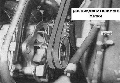
4. Turn the engine in the normal direction (see section General information at the beginning of the Chapter), bring the piston of the first cylinder to the TDC position at the end of the compression stroke. In this case, the timing mark on the crankshaft pulley should align with the zero mark on the timing cover (see accompanying illustration), and the two valves of the sixth cylinder take overlapping positions: one, immediately preceding closing, the second - opening.
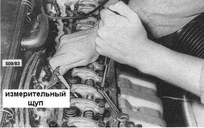
5. Using a 0.38 mm blade of a feeler gauge, evaluate the gap between the end of the intake valve stem of the first cylinder and the working surface of its rocker arm (see accompanying illustration). The blade should pass through the gap with slight resistance.
6. If adjustment is necessary, loosen the rocker arm adjusting screw lock nut and rotate the screw until the desired result is achieved. After securing the screw in the selected position, tighten the lock nut. Check the clearance again with a feeler gauge after tightening the lock nut.
7. Proceeding in a similar manner, check and adjust the clearances of the following valves: exhaust valves of the first, third and fifth cylinders, intake valves of the second and fourth cylinders.
8. Turn the crankshaft one full revolution in the direction of normal rotation so that the piston of the sixth cylinder moves to the TDC position of the end of the compression stroke. The valves of the first cylinder will occupy the above-mentioned overlap position accordingly.
9. Now check and adjust the clearances of the exhaust valves of the second, fourth and sixth cylinders and the intake valves of the third, fifth and sixth.
10. Reinstall the cylinder head cover, replacing the sealing gasket if necessary, and the air intake hose.
11. Start the engine and check the cylinder head cover for signs of leaks. If any are found, eliminate the cause.