


Note: Check valve clearances after removing and installing camshafts, valve components, or when symptoms indicate clearance problems (for example, with high mileage).
1. Warm up the engine and turn it off.
2. Remove the right front wheel arch liner (see Chapter Body) and the cylinder head cover (see section Removal and installation the cylinder head cover).
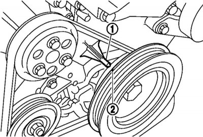
3. Turn the crankshaft pulley clockwise until the TDC mark (2) on the pulley aligns with the TDC indicator (1) on the front cylinder block cover.
4. Working projections of all cams (2 for intake and 2 for exhaust) valve drive first the cylinders must be facing outwards (as a continuation of the valve axis). Otherwise, turn the crankshaft pulley one more revolution.
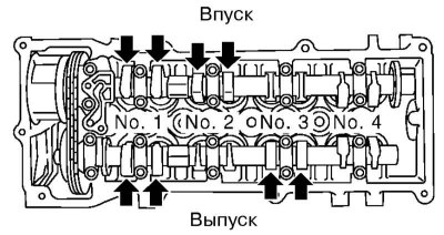
5. Using a blade type feeler gauge, measure the clearances between the cam lobes and the corresponding valve lifters shown in the illustration. Record the results and rotate the crankshaft pulley one more revolution. Measure the remaining valve clearances.
6. Compare the obtained data with the requirements Specifications (for a warm engine) and adjust the valve clearances if necessary as described below.
7. Adjustment of valve clearances is performed by selecting valve tappets. Adjustment of valve clearances, as well as measurement of the working wall thickness of the tappets, should be performed with a warmed-up engine.
8. Remove the appropriate camshaft (see section Removal, inspection and installation of camshafts) and remove the corresponding pushers.
9. Measure the thickness of the middle part of the working wall of the pusher with a micrometer and record the obtained value.
10. To calculate the thickness of the working wall of the required tappet, add the measured valve clearance to the measured thickness of the working wall of the old tappet and subtract the standard valve clearance from the result (see Specifications).
11. The thickness of the tappet working wall can be identified by the two-digit numeric mark stamped on the inner side of the working wall. The mark means hundredths of a wall thickness of 3 mm, for example, the mark "04" corresponds to a wall thickness of 3.04 mm. Valve tappets with a working wall thickness from 3.00 to 3.68 mm in increments of 0.02 mm are available.
12. Install the selected tappet and camshaft.
13. Turn the crankshaft manually a few revolutions and measure the valve clearance (when the engine is cold). Adjust it again if necessary.
14. After completing the adjustment, make sure that the valve clearances meet the requirements Specifications with a warm engine.