Timing Chain Installation Components
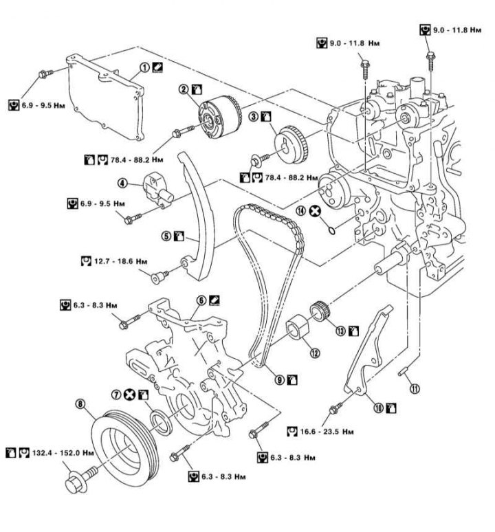
1 - Front cover of the cylinder head; 2/3 - Intake / exhaust camshaft sprocket; 4 - Timing chain tensioner; 5 - Timing chain tensioner lever; 6 - Front cover of the cylinder block; 7 - Front crankshaft oil seal; 8 - Crankshaft pulley; 9 - Timing chain; 10 - Timing chain guide; 11 - Pin; 12 - Oil pump drive sleeve; 13 - Crankshaft sprocket; 14 - O-ring
On models with RKPP remove the power unit and separate the engine from the manual transmission (see Section Removal and installation of the power unit). Then remove the components indicated in paragraph 3 and go to point 5.
Removing
1. Remove the right front wheel and the right front wheel arch locker.
2. Drain the engine oil (see chapter Vehicle settings and routine maintenance).
3. Remove the following components:
- Accessory drive belts and intermediate pulleys of these belts (see Section Replacing accessory drive belts and intermediate belt rollers);
- cylinder head cover (see Section Removal and installation of a cover of a head of cylinders);
- Front exhaust pipe (see chapter Power supply and exhaust systems);
- Starter (see chapter Engine Electrical Systems);
- Both sump sections and oil pickup (see Section Removal and installation of the oil pan and oil intake);
- right headlight (see chapter Onboard electrical equipment).
4. Secure the engine by installing lifting eyes on it and hanging it on a winch. Alternatively, you can support the engine with a jack. Remove the right engine mount and both right mount brackets (see Section Removal and installation of the power unit).
5. Remove generator (see chapter Engine Electrical Systems) and front cylinder head cover (see Section Removal, check and installation of camshafts).
6. Turn out auxiliary bolts of a head of cylinders.
7. Set the piston of the first cylinder to the TDC position, as described in Section Removal, check and installation of camshafts.
8. Using the starter mounting hole, install a retainer on the flywheel ring gear to prevent crankshaft rotation. Alternatively, you can block the crankshaft counterweight with a hammer handle after removing the top section of the oil pan.
9. Turn out a bolt of a cranked shaft.
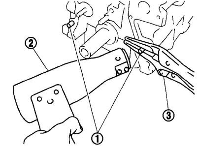
Note. Do not unscrew the fixing bolts, as they will be used as supports for the pulley puller.
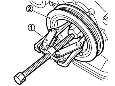
10. Install puller arms (1) into the groove of the pulley (2) crankshaft and remove the pulley.
11. Remove from the front cover of the cylinder block assemblies of the brackets of the intermediate pulleys of the auxiliary drive belts (see Section Replacing accessory drive belts and intermediate belt rollers).
12. Carefully, being careful not to damage the front oil seal or bushing, remove the oil pump drive bushing using long pliers or two screwdrivers.
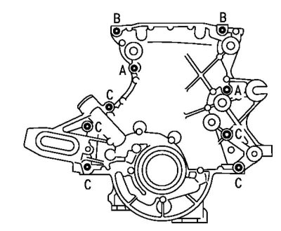
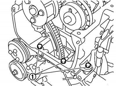
13. Turn out bolts AC specified on an illustration and remove a forward cover of the block of cylinders.
Note. Be careful not to damage the front of the cylinder head gasket. If this happens, replace the gasket (see Section Removal and installation, disassembly and assembly of the cylinder head).
14. Remove the sealing ring from the cylinder block.
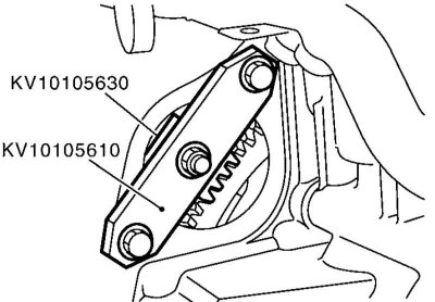
15. Warm up the pins (1) front cover of the block with a hair dryer (2) and remove the pins with pliers (3).
16. Remove the front oil seal by pushing it out with a screwdriver from inside the front cover.
17. As described in Section Removal, check and installation of camshafts, set the intake valve timing to the maximum advance position, remove the timing chain tensioner and camshaft sprockets.
Note. In this case, it is not required to make marks on the chain.
18. Remove the chain, chain guide and tensioner arm. Check the chain for cracks and worn rivets.
19. Remove the crankshaft sprocket.
Installation
Installation of sprockets, chain, its guide and tensioner lever
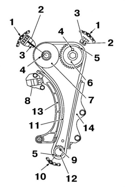
1 - Lilac or orange link; 2 - Outer circle; 3 - risk; 4 - Camshaft pin; 5 - Embossed mark; 6 - Asterisk of an exhaust shaft; 7 - Intake shaft sprocket; 8 - Timing chain tensioner; 9 - Crankshaft key; 10 - Blue link; 11 - Timing chain; 12 - Crankshaft sprocket; 13 - Chain tensioner lever; 14 - Chain guide
1. Completely clean the mating surfaces of all removed parts from the remnants of the old gasket.
2. Install the sprockets, timing chain, its guides and tensioner so that the various marks on them are located in accordance with the illustration above and are facing outward.
Note. Install these components in the following sequence: crankshaft sprocket and chain, tensioner arm, chain guide, camshaft sprockets, chain tensioner.
3. Temporarily install the oil pump drive bushing, crankshaft pulley and pulley mounting bolt so that the crankshaft can be rotated.
4. Turn the crankshaft clockwise and set the inlet valve timing to the maximum retard position (see Section Removal, check and installation of camshafts).
5. Once again turn the crankshaft a few turns clockwise and make sure that the timing marks match.
6. Remove the crankshaft pulley and oil pump drive sleeve.
7. Using a suitable drift or a piece of pipe of suitable diameter, press the front oil seal into the front cover of the cylinder block with the embossing outward.
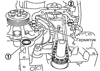
8. Install on block new sealing ring (1) and using a screwdriver, apply sealant to the joint between the cylinder head gasket and the cylinder block in two places (2).
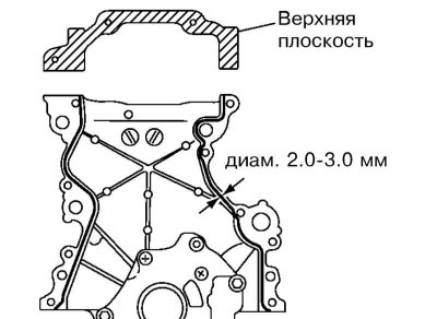
9. Apply sealant to the rear of the front cover of the cylinder block and to the top plane of the front cover.
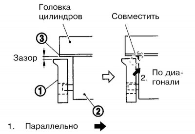
10. As shown in the illustration, install the front cover (1) as tight as possible to the cylinder block (2), moving it parallel to the crankshaft and be sure to leave a small gap between the cover and the gasket (3) cylinder heads. Then slide the cover diagonally to the junction of the block and cylinder head so that the cover is mated with the cylinder head gasket.
11. Temporarily secure the front cover with a few bolts and press the pins through it into the cylinder block.
 |  |
12. Temporarily tighten the front cover mounting bolts and the auxiliary cylinder head bolts. Then tighten the indicated bolts to the required torque.
13. Align the flat surfaces of the oil pump drive bushing with its inner gear and install the bushing being careful not to damage the front oil seal.
Note. If necessary, turn the internal gear of the pump with a screwdriver.
14. Install the accessory drive belt idler pulley bracket assemblies (see Section Replacing accessory drive belts and intermediate belt rollers).
15. Establish a pulley of a cranked shaft and tighten a bolt of its fastening.
Note. In this case, the crankshaft must be blocked, as when removing the pulley.
16. Install the front cylinder head cover (see Section Removal, check and installation of camshafts).
17. Establish an arm and a rack of the right support of the engine.
18. Further installation is carried out in the reverse order of the dismantling of the components.
19. At least 30 minutes after installation, warm up the engine and check for engine oil leaks.