


Engine repair HR cars Nissan Note 1

Checking drive belts
The check should only be carried out on a cold engine or 30 minutes after the engine has been stopped. 1. Generator; 2. Water pump; 3. Crankshaft pulley; 4. Air...
The check should only be carried out on a cold engine or 30 minutes after the engine has been stopped. 1. Generator; 2. Water pump; 3. Crankshaft pulley; 4. Air...

Adjusting the drive belt tension
Component Location of the adjusting bolt and method of tensioning the belt Drive belt Adjusting bolt on the tension pulley Attention: When replacing the belt with a new...
Component Location of the adjusting bolt and method of tensioning the belt Drive belt Adjusting bolt on the tension pulley Attention: When replacing the belt with a new...

Removal and installation drive belts
Removal 1. Remove the protective cover from the front right fender. See chapter Body . 2. Loosen the lock nut (A) of the tension pulley and adjust the belt tension by...
Removal 1. Remove the protective cover from the front right fender. See chapter Body . 2. Loosen the lock nut (A) of the tension pulley and adjust the belt tension by...
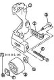
Removal and installation the drive belt tension pulley
Removal 1. Remove the drive belts. See section " Removal and installation ". 2. Unscrew the lock nut, remove the plate (7), tension pulley (6) and washer (5). 3. Remove...
Removal 1. Remove the drive belts. See section " Removal and installation ". 2. Unscrew the lock nut, remove the plate (7), tension pulley (6) and washer (5). 3. Remove...

Air Cleaner and Duct — Components
1. Air cleaner filter element; 2. Air mass flow sensor; 3. O-ring seal; 4. Holder; 5. Air cleaner cover; 6. Air duct; 7. PCV hose; 8. Clamp; 9. Air duct (inlet); 10....
1. Air cleaner filter element; 2. Air mass flow sensor; 3. O-ring seal; 4. Holder; 5. Air cleaner cover; 6. Air duct; 7. PCV hose; 8. Clamp; 9. Air duct (inlet); 10....

Air Cleaner and Duct — Removal and Installation
Removal 1. Remove the air duct (inlet). 2. Remove the air cleaner filter element from the air cleaner housing. See section " Replacing the air cleaner filter element "....
Removal 1. Remove the air duct (inlet). 2. Remove the air cleaner filter element from the air cleaner housing. See section " Replacing the air cleaner filter element "....

Replacing the air cleaner filter element
Removal 1. Press the latches (A) on both sides of the air cleaner cover (1) inward (B). 2. Pull the air cleaner cover forward (C) and remove it (see fig.). 3. Remove the...
Removal 1. Press the latches (A) on both sides of the air cleaner cover (1) inward (B). 2. Pull the air cleaner cover forward (C) and remove it (see fig.). 3. Remove the...

Upper Intake Manifold — Components
1. EVAP hose; 2. Vacuum tank; 3. EVAP hose; 4. O-ring seal; 5. EVAP carbon canister purge solenoid valve; 6. Electric throttle actuator; 7. Water hose; 8. Water hose; 9....
1. EVAP hose; 2. Vacuum tank; 3. EVAP hose; 4. O-ring seal; 5. EVAP carbon canister purge solenoid valve; 6. Electric throttle actuator; 7. Water hose; 8. Water hose; 9....
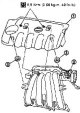
Removal and installation the upper part of the intake manifold
Removal 1. Remove the cover (1) from the engine. 2. Upper part of the intake manifold 3. Rubber bushing 2. Disconnect the air duct (inlet) and the air duct (between the...
Removal 1. Remove the cover (1) from the engine. 2. Upper part of the intake manifold 3. Rubber bushing 2. Disconnect the air duct (inlet) and the air duct (between the...

Exhaust Manifold — Components
1. Exhaust manifold cover; 2. Exhaust manifold cover; 3. Wiring bracket; 4. Heated oxygen sensor 1; 5. Exhaust manifold stand; 6. Exhaust manifold; 7. Gasket; 8....
1. Exhaust manifold cover; 2. Exhaust manifold cover; 3. Wiring bracket; 4. Heated oxygen sensor 1; 5. Exhaust manifold stand; 6. Exhaust manifold; 7. Gasket; 8....

Removal and installation the exhaust manifold
Removal 1. Disconnect the front exhaust pipe. See chapter Accelerator, fuel system and exhaust system . 2. Remove the heated oxygen sensor 1 wiring bracket from the...
Removal 1. Disconnect the front exhaust pipe. See chapter Accelerator, fuel system and exhaust system . 2. Remove the heated oxygen sensor 1 wiring bracket from the...

Oil pan and coarse oil filter — components
1. Rear oil seal; 2. O-ring seal; 3. Oil pan (upper); 4. Chain tensioner; 5. Oil pump drive chain; 6. Crankshaft sprocket; 7. Oil pump sprocket; 8. Oil pan drain plug;...
1. Rear oil seal; 2. O-ring seal; 3. Oil pan (upper); 4. Chain tensioner; 5. Oil pump drive chain; 6. Crankshaft sprocket; 7. Oil pump sprocket; 8. Oil pan drain plug;...

Removal and installation the oil pan and coarse oil filter
Note: The coarse oil filter and oil pump are part of the oil pan (upper) and cannot be disassembled separately. Removal Note: When removing only the oil pan (lower),...
Note: The coarse oil filter and oil pump are part of the oil pan (upper) and cannot be disassembled separately. Removal Note: When removing only the oil pan (lower),...

Ignition Coils — Components, Removal and Installation
Caution: Do not drop or hit it. Do not disassemble. Removal 1. Remove the upper intake manifold. See section " Upper part of the intake manifold ". 2. Disconnect the...
Caution: Do not drop or hit it. Do not disassemble. Removal 1. Remove the upper intake manifold. See section " Upper part of the intake manifold ". 2. Disconnect the...

Spark Plugs (with Platinum Tips) — Components, Removal and Installation
Removal 1. Remove the upper intake manifold. See section " Upper part of the intake manifold ". 2. Remove the ignition coil. See section " Ignition coil ". 3. Remove the...
Removal 1. Remove the upper intake manifold. See section " Upper part of the intake manifold ". 2. Remove the ignition coil. See section " Ignition coil ". 3. Remove the...

Fuel injectors and fuel line — components
1. Quick release nipple cap; 2. Fuel hose; 3. Fuel pipe; 4. Fuel pipe protective cover; 5. O-ring (black); 6. Clamp; 7. Fuel injector; 8. O-ring (green) Caution: Do not...
1. Quick release nipple cap; 2. Fuel hose; 3. Fuel pipe; 4. Fuel pipe protective cover; 5. O-ring (black); 6. Clamp; 7. Fuel injector; 8. O-ring (green) Caution: Do not...

Fuel injectors and fuel line — removal and installation
Attention: When carrying out work in the service station premises, hang up a sign saying "FIRE HAZARD". Carry out work in a well-ventilated area. Have a CO₂ fire...
Attention: When carrying out work in the service station premises, hang up a sign saying "FIRE HAZARD". Carry out work in a well-ventilated area. Have a CO₂ fire...

Valve Cover — Components
1. PCV hose; 2. Oil filler cap; 3. Valve cover; 4. Bracket; 5. Rubber bushing; 6. PCV valve; 7. PCV hose; 8. PCV hose; A. To the air duct
1. PCV hose; 2. Oil filler cap; 3. Valve cover; 4. Bracket; 5. Rubber bushing; 6. PCV valve; 7. PCV hose; 8. PCV hose; A. To the air duct

Valve cover — removal and installation
Removal 1. Remove the upper intake manifold. See section " Upper part of the intake manifold ". 2. Remove the ignition coil. See section " Ignition coil ". 3. Remove the...
Removal 1. Remove the upper intake manifold. See section " Upper part of the intake manifold ". 2. Remove the ignition coil. See section " Ignition coil ". 3. Remove the...

Timing chain — components
1. Chain guide at the bend; 2. Timing chain tensioner; 3. Exhaust camshaft sprocket; 4. Intake camshaft sprocket; 5. Plug; 6. Front oil seal; 7. Crankshaft pulley; 8....
1. Chain guide at the bend; 2. Timing chain tensioner; 3. Exhaust camshaft sprocket; 4. Intake camshaft sprocket; 5. Plug; 6. Front oil seal; 7. Crankshaft pulley; 8....

Timing chain — removal and installation
Note: The direction of rotation indicated in the text refers to the rotation as viewed from the front of the engine. Removal 1. Remove the front right wheel. 2. Remove...
Note: The direction of rotation indicated in the text refers to the rotation as viewed from the front of the engine. Removal 1. Remove the front right wheel. 2. Remove...

Camshafts — Components
1. Brackets (No. 2-5) of camshafts; 2. Bracket No.1 of camshafts; 3. Camshaft sprocket (outlet); 4. Camshaft sprocket (intake); 5. Cylinder head; 6. Oil filter (for...
1. Brackets (No. 2-5) of camshafts; 2. Bracket No.1 of camshafts; 3. Camshaft sprocket (outlet); 4. Camshaft sprocket (intake); 5. Cylinder head; 6. Oil filter (for...

Camshafts — removal and installation
Note: The direction of rotation indicated in the text refers to the rotation as viewed from the front of the engine. Removal Note: This section describes the procedure...
Note: The direction of rotation indicated in the text refers to the rotation as viewed from the front of the engine. Removal Note: This section describes the procedure...

Camshafts — valve clearances
Examination If the camshaft or valve related components are removed, installed or replaced, or if engine operation deviates from the normal range over time due to...
Examination If the camshaft or valve related components are removed, installed or replaced, or if engine operation deviates from the normal range over time due to...

Removal and installation the valve seal
Removal 1. Remove the camshaft. See section " Camshaft ". 2. Remove the valve lifters. See section " Camshaft ". 3. Turn the crankshaft until the piston of the cylinder...
Removal 1. Remove the camshaft. See section " Camshaft ". 2. Remove the valve lifters. See section " Camshaft ". 3. Turn the crankshaft until the piston of the cylinder...

Removal and installation the front oil seal
Removal 1. Remove the following components: protective cover from the front right wing; see chapter Body ; drive belts; see section " Drive belts "; crankshaft pulley;...
Removal 1. Remove the following components: protective cover from the front right wing; see chapter Body ; drive belts; see section " Drive belts "; crankshaft pulley;...

Removal and installation the rear oil seal
Removal 1. Remove the gearbox assembly. See chapters Manual transmission and automatic transmission . 2. Remove the clutch housing and driven disc. See chapter Clutch ....
Removal 1. Remove the gearbox assembly. See chapters Manual transmission and automatic transmission . 2. Remove the clutch housing and driven disc. See chapter Clutch ....

Cylinder head service on car
Compression check 1. Warm up the engine well. Then turn it off. 2. Relieve the fuel pressure. See chapter Engine management system . 3. To prevent fuel injection during...
Compression check 1. Warm up the engine well. Then turn it off. 2. Relieve the fuel pressure. See chapter Engine management system . 3. To prevent fuel injection during...

Cylinder head — removal and installation
1. Cylinder head assembly; 2. Cylinder head bolt; 3. Washer; 4. Cylinder head gasket Removal 1. Relieve the fuel pressure. See chapter Engine management system . 2....
1. Cylinder head assembly; 2. Cylinder head bolt; 3. Washer; 4. Cylinder head gasket Removal 1. Relieve the fuel pressure. See chapter Engine management system . 2....

Cylinder Head — Components
1. Spark plug; 2. Rusks; 3. Valve spring plate; 4. Valve spring; 5. Valve spring seat; 6. Valve seal; 7. Valve guide (outlet); 8. Valve guide (intake); 9. Cylinder head;...
1. Spark plug; 2. Rusks; 3. Valve spring plate; 4. Valve spring; 5. Valve spring seat; 6. Valve seal; 7. Valve guide (outlet); 8. Valve guide (intake); 9. Cylinder head;...

Cylinder head — disassembly and assembly
Disassembly 1. Remove the spark plugs using a wrench (suitable special tool). 2. Remove the valve lifters. Mark the locations and place the components in order without...
Disassembly 1. Remove the spark plugs using a wrench (suitable special tool). 2. Remove the valve lifters. Mark the locations and place the components in order without...

Engine Assembly — Components
1. Left engine mount insulator; 2. Left engine support bracket.; 3. Right engine mount insulator; 4. Right engine support stand; 5. Right engine support bracket; 6. Rear...
1. Left engine mount insulator; 2. Left engine support bracket.; 3. Right engine mount insulator; 4. Right engine support stand; 5. Right engine support bracket; 6. Rear...

Engine assembly — removal and installation
Stop the vehicle on a level, firm surface. Place chocks under the rear wheels at the front and rear. If the engine is not equipped with lifting eyes, select them and...
Stop the vehicle on a level, firm surface. Place chocks under the rear wheels at the front and rear. If the engine is not equipped with lifting eyes, select them and...
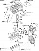
Cylinder Block — Components
1. Crankshaft angle sensor (POS) cover; 2. Crankshaft angle sensor (POS); 3. O-ring seal,; 4. Drain plug; 5. Cylinder block; 6. Oil dipstick; 7. Oil dipstick guide; 8....
1. Crankshaft angle sensor (POS) cover; 2. Crankshaft angle sensor (POS); 3. O-ring seal,; 4. Drain plug; 5. Cylinder block; 6. Oil dipstick; 7. Oil dipstick guide; 8....

Cylinder block — disassembly and assembly
Disassembly Note: The following describes disassembly using a stand for an engine with a mount on the gearbox side. If another type of stand is used, please note the...
Disassembly Note: The following describes disassembly using a stand for an engine with a mount on the gearbox side. If another type of stand is used, please note the...

The order of selection of pistons and bearings
Description Correspondence Selected component Selection criteria Method of selection Between the cylinder block and the crankshaft Main bearing Main bearing class...
Description Correspondence Selected component Selection criteria Method of selection Between the cylinder block and the crankshaft Main bearing Main bearing class...

Cylinder Block — Checking After Disassembly
Crankshaft axial play Using a dial indicator (A), measure the clearance between the thrust bearings and the crank arm by moving the crankshaft back and forth. Standard:...
Crankshaft axial play Using a dial indicator (A), measure the clearance between the thrust bearings and the crank arm by moving the crankshaft back and forth. Standard:...
This section is available on: russian, bulgarian, belarusian, ukrainian, serbian, croatian, romanian, polish, slovak, hungarian
Similar information for other Nissan models
➜ Power unit: Engine repair 4.2 l Nissan Patrol 4 (1987-1997, petrol)
➜ Power unit: Petrol engines (2.0) Nissan Sunny 7 (1990-1998)
➜ Power unit: Engine repair Nissan Almera 1 (1995-2000)
➜ Power unit: Engine repair Nissan Primera 1 (1990-1996, petrol)
➜ Power unit: Engines 4-cylinder Nissan Terrano 1 (1986-1995, petrol)
➜ Powertrain QR25DE: Engine repair Nissan X-Trail 2 (2007-2013, petrol)
Link in different formats to this section
TEXTHTMLBB Code
- User manual
- Control devices
- Preparing to move
- Starting engine and driving
- Maintenance
- Technical information
- Power unit
- Engine repair CR
- Engine repair HR
- Engine lubrication system
- Cooling system (CR)
- Cooling system (HR)
- Fuel and exhaust system
- Engine management (CR)
- Engine management (HR)
- Transmission
- Clutch
- Mechanical gearbox
- Automatic gearbox
- Drive shafts and axles
- Chassis
- Car suspension
- Brake system
- Steering
- Body
- Airbags (SRS)
- Doors, hood and locks
- Glasses and mirrors
- Exterior (external elements)
- Interior (internal elements)
- Air conditioning automatic
- Electrical equipment
- Equipment and devices
- Launch and charge system
- Headlights and lighting
- Windshield wipers and washers
- General information
- Introduction to guide
- Governing bodies
- Starting engine and driving
- Maintenance
- Power unit
- Engine repair
- Cooling system
- Heating and ventilation
- Power and exhaust system
- Ignition system
- Charge and launch systems
- Transmission
- Mechanical gearbox
- Automatic gearbox
- Clutch
- Drive shafts and hubs
- Chassis
- Brake system
- Car suspension
- Steering
- Body
- Exterior (external elements)
- Interior (internal elements)
- Electrical equipment
- Equipment and devices
- Electrical circuits
Cookies are used to improve the site's performance. 💻 Continue by agreeing to the terms.