Attention: The direction of rotation given in the text refers to rotation as viewed from the front of the motor.
Removing
1. Remove the front right wheel.
2. Remove the protective pad from the front right fender. See chapter Body.
3. Drain the engine oil. See chapter Lubrication system and engine cooling system.
Note: Perform this operation when the engine is cold.
4. Remove the following components:
- valve cover; see section «Valve lid»;
- drive belts; see section «Drive belts»;
- water pump pulley; see chapter Lubrication system and engine cooling system;
- earth cable (between right engine mount bracket and radiator core support).
5. Support the bottom of the engine with a telescoping stand, then remove the right engine support bracket and insulator. See section «Complete engine».
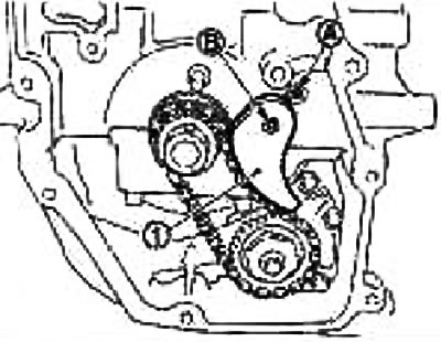
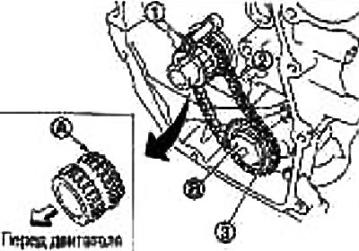
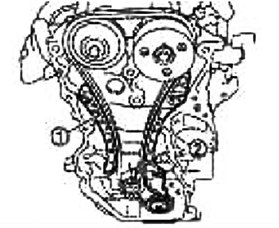
6. Set the piston of cylinder No. 1 to TDC in the compression stroke next, as follows:
- A. Check crankshaft pulley (2) clockwise and align the timing mark (colorless risk) (A) with sync pointer (1) on the front cover.
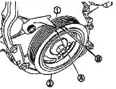
B. White paint mark (not used for maintenance).
- b. Make sure the alignment marks on the camshaft sprockets are aligned as shown.

1. Exhaust camshaft sprocket
2. Intake camshaft sprocket
(A) Alignment mark (knocked out)
(B) Alignment mark (risk carved on the periphery)
Otherwise, turn the crankshaft pulley one more turn and align the marks as shown in the figure.
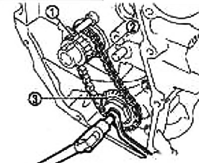
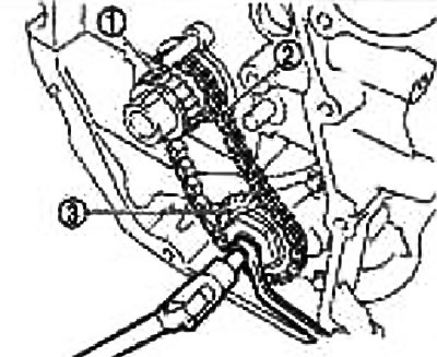
7. Remove the crankshaft pulley as follows:
- A. Fix the crankshaft pulley (1) holder (suitable special tool) (A).
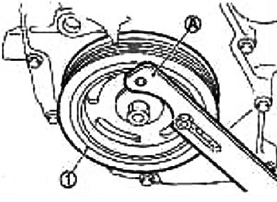
- b.Loosen the crankshaft pulley bolts so that they move away from their original position.
Attention: Do not unscrew the crankshaft pulley bolts, as they will serve as a fulcrum for the pulley puller (special tool: KV111030000).
- With. Attach the crankshaft pulley puller (special tool: KV111030000) in the M6 holes of the crankshaft pulley and remove the crankshaft pulley
V. Bolt M6
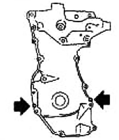
8. Remove the front cover as follows:
- A. Loosen the mounting bolts in the reverse order of the figure.
- b. Pry off the cover at the points indicated by the arrows in the figure, cut off the sealant and remove the front cover.
9. Remove the front oil seal from the chain front cover using a suitable tool.
Attention: Be careful not to damage the front cover.
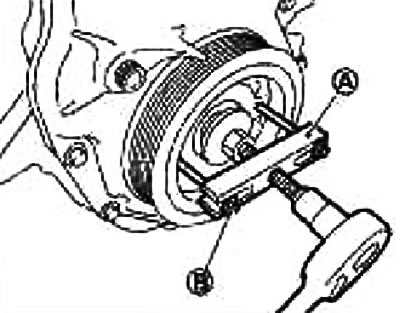
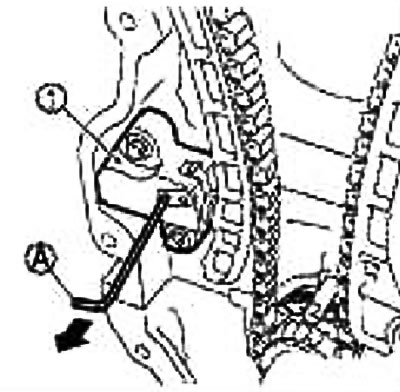
10. Remove the chain tensioner as follows:
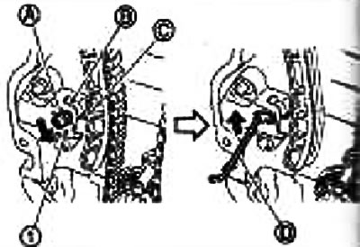
- A. Fully push the lever (A) chain tensioner and release the plunger (WITH) inside the tensioner.
Locking tab (IN) plunger can be released by fully pushing the lever (coaxial with lever design).
- b. Pull back the lever and align the hole in it with the hole in the housing.
By aligning the holes in the lever and the housing, the plunger can be fixed.
When the protrusions of the plunger ratchet and locking tab face each other, the holes are not aligned. Engage them correctly and align these holes by moving the plunger slightly.
- With. Insert locking pin (D) into the hole in the tensioner housing through the hole in the lever and lock the lever in the up position.
As an example, a hex wrench is used instead of a locking pin (2.5mm).
- d. Remove chain tensioner
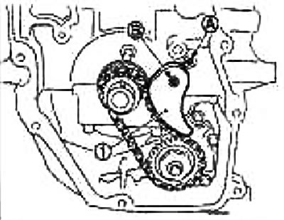
11. Remove tensioner guide (2) and the timing chain guide at the bend (1).
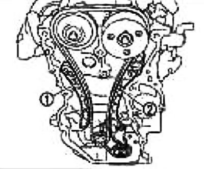
12. Remove the timing chain (2).
Tighten the timing chain from the sprocket side of the exhaust camshaft (1) and start removing the chain from that side.
Attention: After removing the timing chain, do not turn the crankshaft or camshaft separately, otherwise the valves will hit the piston crowns.
13. Remove the sprocket from the crankshaft and components associated with the oil pump drive chain as follows:
- A. Remove chain tensioner (1).
Remove from axle (IN) and from the mounting hole of the spring (A).
- b. Holding the tip of the oil pump shaft with a TORX socket (size: E8), loosen the oil pump sprocket nuts and unscrew them.
- With. Remove the crankshaft sprocket at the same time (1), oil pump drive chain (2) and oil pump sprocket (3).
Check after removal
Valve train chain
Check for cracks (A) or excessive wear (IN) on the roller links of the timing chain. Replace timing chain if necessary.
Installation
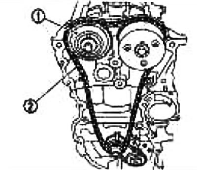
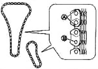
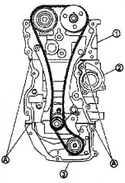
Note: The illustration shows the relative position of the alignment marks on the chains and on the corresponding sprockets after the components have been installed.
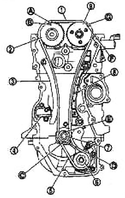
1. Timing chain.; 2. Camshaft sprocket (release); 3. Timing chain guide at the bend; 4. Timing chain tensioner; 5. Oil pump drive chain; 6. Oil pump sprocket; 7. Crankshaft sprocket; 8. Timing chain tensioner guide; 9. Camshaft sprocket (inlet); A. Link yellow; B. Registration mark (knocked out); C. Orange link; D. Registration mark (knocked out); E. Crankshaft key (facing straight up); F. Registration mark (risk carved on the periphery); G. Link yellow
1. Install the crankshaft sprocket and components related to the oil pump drive chain as follows:
- A. Install the crankshaft sprocket at the same time (1), oil pump drive chain (2) and oil pump sprocket (3).
Fit the crankshaft sprocket with the teeth under the oil pump sprocket (A) toward the rear of the engine.
Fit the oil pump sprocket with a hexagonal face (IN) towards the front of the engine.
Note: There are no alignment marks on components related to the oil pump drive chain.
- b. Holding the tip of the oil pump shaft with a TORX socket (size: E8), tighten the oil pump sprocket nuts.
1. Crankshaft sprocket; 2. Oil pump drive chain; 3. Oil pump sprocket
- With. Install the chain tensioner (1).
Put the body on the axle (IN), by inserting the spring into the mounting hole (A) on the front surface of the cylinder block fig.
2. Put on the timing chain as follows:
Fit the timing chain by lining up the marks on each sprocket and timing chain.
If the marks do not line up, rotate the camshaft slightly and align.
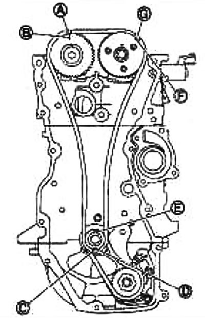
A. Link yellow; B. Registration mark (knocked out); C. Orange link; D. Registration mark (knocked out); E. Crankshaft key (facing straight up); F. Registration mark (risk carved on the periphery); G. Link yellow
Attention:
- After aligning the marks, hold them in this position while holding the timing chain with your hand.
- To prevent misalignment of the teeth, do not rotate the crankshaft and camshaft until the front cover is installed.
3. Install tensioner guide (2) and chain guide at the bend (1).
4. Install chain tensioner (1).
Push the plunger in and hold it down with the locking pin (A).
After installing the chain tensioner, carefully remove the lock pin.
5. Check again that the alignment marks on the sprockets and timing chain have not shifted.
6. Insert the front oil seal into the front cover.
7 Install the front cover as follows:
- A. Apply the sealant in a continuous bead using a syringe (special tool: WS39930000) on the front cover as shown in the figure.
Use branded sealant or equivalent
1. Cylinder head; 2. Cylinder block; 3. Oil pan (upper); A. Sealant application area. Diameter 3.0-4.0mm
- b. Apply the sealant in a continuous bead using a syringe (special tool: WS39930000) on the front cover as shown in the figure.
Use branded sealant or equivalent
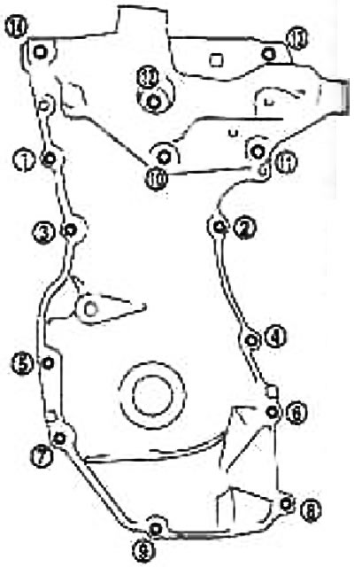
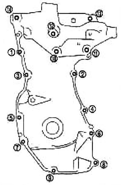
- With. Tighten the bolts in the order indicated by the numbers in the figure.
- d. After tightening, tighten them with the required torque in the order indicated by the numbers in Figure No. 2.
Attention: Remove excess sealant that has come out on the surface.

A. Sealant application area. Diameter 3.0-4.0mm
8. Install the crankshaft pulley, aligning it with the key.
Pressing the crankshaft pulley with a plastic hammer, strike the center section (not around the circle).
Caution: Install the crankshaft pulley without damaging the lip of the front oil seal.
9. Tighten the crankshaft pulley mounting bolt as follows:
Fix the crankshaft pulley with the pulley holder (suitable special tool) and tighten the crankshaft pulley mounting bolt.
- A. Apply fresh engine oil to the threads and seating surface of the crankshaft pulley bolt.
- b. Tighten the crankshaft pulley mounting bolt.
Tightening torque: 35.0 Nm (3.6 kg m)
Mark with paint (IN) on the crankshaft pulley opposite any corner mark (A) on the flange (1) crankshaft pulley bolt.
- d. Tighten the bolt by 60° (corner tightening).
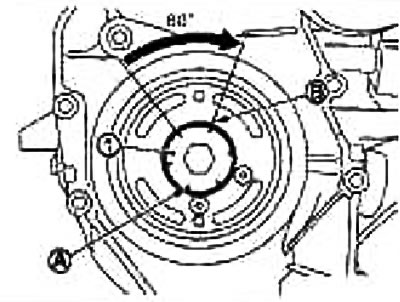
Control the tightening angle by the corner marks.
10. Turn the crankshaft pulley clockwise by hand and check that it rotates freely.
11. After this operation, installation is carried out in the reverse order of removal.
Check after installation
Leak Check
The following are procedures for checking fluid, engine oil, and exhaust leaks.
Before starting the engine, check the oil/fluid levels, including engine coolant and engine oil. If the level is below normal, add and bring to the required level. See chapter General information and maintenance.
Check for fuel leaks as follows:
- Turn the ignition key to position «ON» (without starting the engine). After pressurizing the fuel lines, check for fuel leaks at the joints.
- Start the engine. While increasing the engine speed, check again for fuel leaks at the fuel line joints.
Let the engine run and check for unusual noise or vibration.
Note: If the hydraulic pressure inside the timing chain tensioner drops after removal/installation, slack in the guide may cause a thud during and immediately after starting the engine. However, this does not indicate a malfunction. The knock will stop when the hydraulic pressure rises.
Warm up the engine well and check for fuel, exhaust, or oil/fluid leaks, including engine coolant and engine oil.
Bleed the pipes and hoses of the relevant systems, such as the cooling system.
After the engine has cooled down, check the oil/fluid levels again, including engine coolant and engine oil. Top up if necessary and bring to the required level.