Removing
1. Remove the front cover.
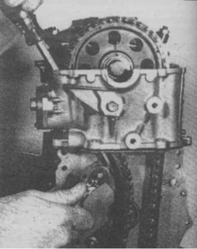
2. Remove the bolts of the tensioner, shoe and damper, remove these parts (photo).
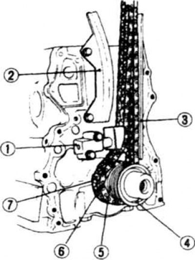
19.2 Camshaft drive chain
1. Tensioner; 2. The damper is left; 3. The damper is right; 4. Oil deflector; 5. Oil pump drive gear; 6. Drive sprocket; 7. Chain
3. Reject the bolt and remove the camshaft sprocket (see above).
4. Remove the chain.
5. Remove the oil deflector, oil pump drive gear, and drive sprocket (photo).
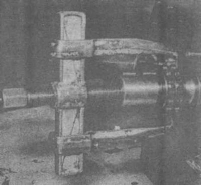
19.5 Removing the drive sprocket
6. Check the condition of the sprocket teeth by comparing the tooth profiles on both sides. Replace sprocket teeth if hooked.
7. The chain is changed along with worn sprockets, or every 48,000 km. The chain should also be replaced if the rollers show signs of wear.
8. Install the sprocket on the camshaft and check its axial play, which should not exceed 0.2 mm.
9. Check the condition of the tensioner and dampers, replace if necessary.
Installation
10. Turn the camshaft so that the valves of the 1st cylinder are closed. Install the crankshaft so that the piston of the 1st cylinder is at TDC.
11. Install dampers.
12. Install the oil deflector, oil pump drive gear, and drive sprocket onto the crankshaft nose. Make sure the alignment marks on the drive sprocket are facing forward (photo).
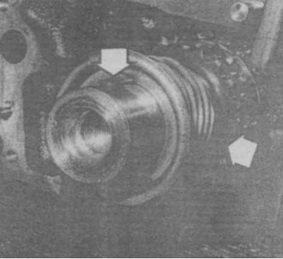
19.12 When assembling, the key must be facing up and the mark on the sprocket must be forward
13. Before installing the chain, turning the crankshaft is not allowed.
14. Put the chain on the camshaft sprocket, then wind it on the drive sprocket. Tighten the camshaft sprocket bolt. Keep the following in mind when assembling:
- A). The crankshaft key must be facing up.
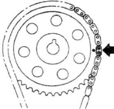
- b). The distinctively colored chain links must be aligned with the marks on the sprockets, and positioned to the right when viewed from the front (photo).
- V). The camshaft locating pin must go into the hole in the sprocket number 2 (photo).
19.14a On the Z24i engine, the chain link with distinctive color must be aligned with the mark on the camshaft sprocket, and the camshaft locating pin must go into hole number 2
19.14v On the K24 engine, the silver-colored link must be aligned with the mark on the camshaft sprocket
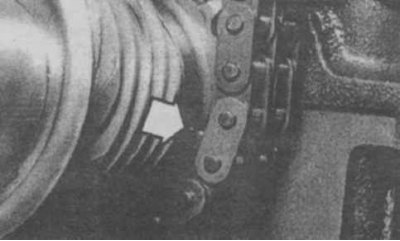
19.14g On all engines, the chain link with a distinctive color must be aligned with the mark on the drive sprocket
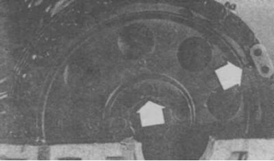
15. Install the tensioner, adjust the position of the left damper so that there is no gap between the tensioner body and the shoe (photo).
19.15a Move the pacifier aside.
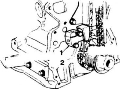
19.15b The gap between the tensioner body and the shoe after assembly must be absent
1. Tensioner; 2. After assembly
16. Install the front cover.