


Valve timing drive details
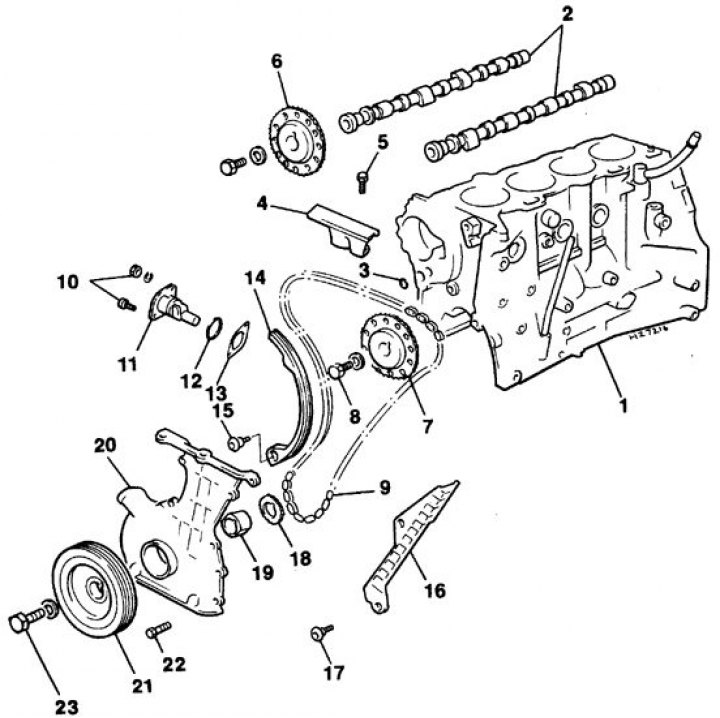
1. Cylinder block; 2. Camshafts; 3. O-ring gasket; 4. Upper chain guide; 5. Upper guide bolt; 6. Intake camshaft sprocket; 7. Exhaust camshaft sprocket; 8. Camshaft sprocket bolt; 9. Chain; 10. Chain tensioner nut and bolt; 11. Tensioner; 12. O-ring gasket; 13. Gasket; 14. Tensioner shoe; 15. Tensioner shoe axle bolt; 16. Calmator; 17. Damper bolt; 18. Crankshaft drive sprocket; 19. Oil pump drive spacer sleeve; 20. Camshaft chain drive cover; 21. Crankshaft pulley; 22. Chain drive cover bolt; 23. Crankshaft pulley bolt
Removal
1. Set the piston of the 1st cylinder to TDC of the compression stroke (see subsection 3.1.1.3).
2. Remove the cylinder head cover (see subsection 3.2.1.4).
3. Remove the camshaft chain drive cover (see subsection 3.2.1.6).
4. Remove the oil filter (see subsection 2.2.1). If the filter is damaged during removal, replace the filter.
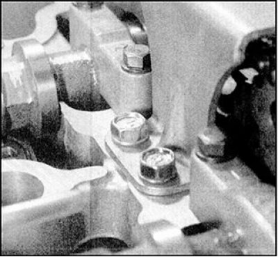
5. Loosen the nuts and bolts and remove the chain tensioner. Remove the tensioner O-ring.
Attention! When removing the tensioner, the crankshaft must not rotate.
 |
 |
6. Loosen the mounting bolts and remove the upper chain guide from the top of the cylinder head.
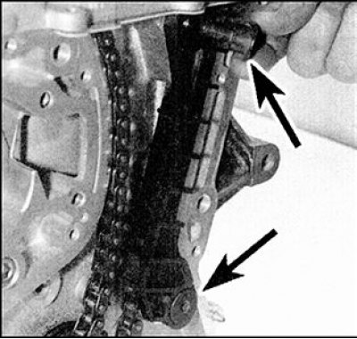
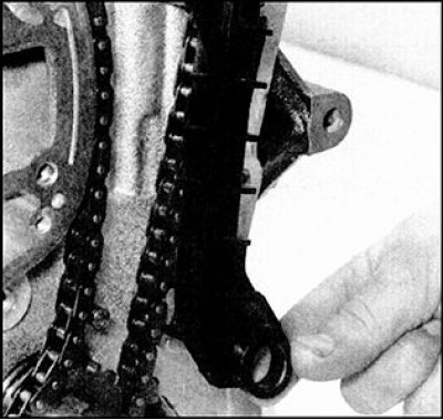
7. Loosen the chain tensioner shoe axle bolt and remove the shoe from the cylinder block.
 |
 |
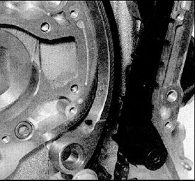
8. Loosen and unscrew the bolts (arrows) and remove the damper.
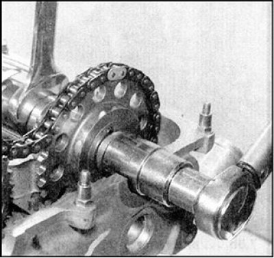
9. Loosen the camshaft sprocket bolts, hold each camshaft with an open-end wrench by the flats at the front, and remove each bolt along with the washer.
10. Remove the sprockets from the camshafts. If the dowel pins at the ends of the camshafts become loose, remove the dowel pins and store them with the sprockets.
11. Remove the chain from the crankshaft drive sprocket.
12. If necessary, remove the sprocket from the crankshaft, first paying attention to the correct position of the sprocket, and remove the key (when the key in the crankshaft groove becomes loose). Store the key together with the drive sprocket.
Checking the status
1. Check the drive and two driven sprockets for signs of wear and defects such as chips, hooks or missing teeth. If any of these signs of wear and damage are found, all sprockets and the chain should be replaced as a set.
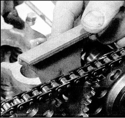
2. Inspect the chain links, check the wear of the rollers. The degree of chain wear can be determined by the deflection in the horizontal plane. In a new chain, there is almost no deflection. If there is noticeable axial play in the chain links, the chain should be replaced. Keep in mind that regardless of the presence of external signs of wear, the chain should also be replaced after a significant mileage, or if a noticeable noise is heard from the chain with the engine running. It is strongly recommended to change the chain complete with sprockets, since installing a new chain on worn sprockets, or vice versa, leads to increased wear of the new part and is not justified in terms of costs. If the condition of the chains and sprockets is in doubt, then contact the Nissan service center for qualified advice.
3. Check for signs of wear or damage on the chain guide and chain guide where it contacts the chain; if any defects are found, replace these parts.
4. The condition of the tensioner can only be assessed by comparison with a new part. If the condition of the tensioner gives rise to even the slightest doubt, it should be replaced.
Installation
1. Make sure that the piston of the 1st cylinder is still at TDC of the compression stroke (the keyway on the crankshaft nose should be facing vertically upwards when viewed from the right side of the engine). Insert the key into the groove on the nose of the crankshaft.
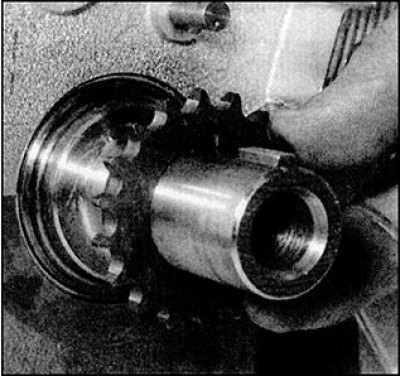
2. Correctly orient the crankshaft drive sprocket (the timing mark on the sprocket should be facing away from the crankshaft, and the groove in the sprocket should be aligned with the key) and put it on the crankshaft.
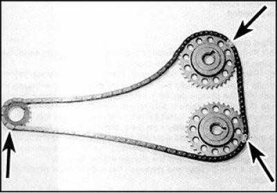
3. The chain has three links of different colors (indicated by arrows), each of which corresponds to a separate installation mark. The two links that are closer to each other correspond to the installation marks of the camshafts, the third link must coincide with the installation mark of the crankshaft drive sprocket.
Caution: On some vehicles, the chain links that correspond to the timing marks on the camshaft sprockets may be a different color than the link that corresponds to the timing mark on the drive sprocket.
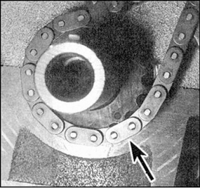
4. Orient the chain so that the colored links are facing outward and are located opposite the corresponding installation marks, and place the chain on the drive sprocket, aligning the highlighted link (arrow) with the installation mark on the sprocket.
5. Install the driven sprockets onto the intake and exhaust camshafts with the timing marks on the sprockets facing outward.
Attention! Both stars are the same.
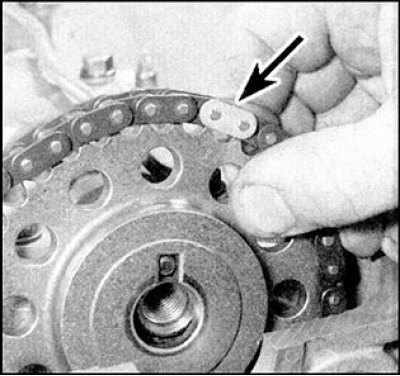
6. Put on the chain (indicated by the arrow) onto the exhaust camshaft sprockets so that the differently colored links align with the timing marks.
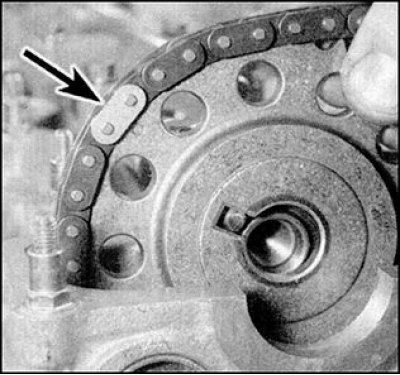
7. Then put on the chain (indicated by the arrow) onto the intake camshaft sprockets, aligning the differently colored links with the installation marks.
8. Insert the dowel pins into the ends of the camshafts (if they were filmed), align the slots in the sprockets with the alignment pins. Make sure that the different colored links align with the corresponding alignment marks on the sprockets. If not, remove the chain from the sprockets and make any necessary adjustments.
9. After aligning the timing marks with the corresponding chain links, tighten the camshaft sprocket bolts, placing washers on the bolts.
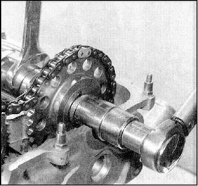
10. Tighten the bolts to the specified torque. While tightening, do not allow the camshaft to turn by holding it by the flats with an open-end wrench.
11. Install the damper and tighten the damper bolt to the specified torque.
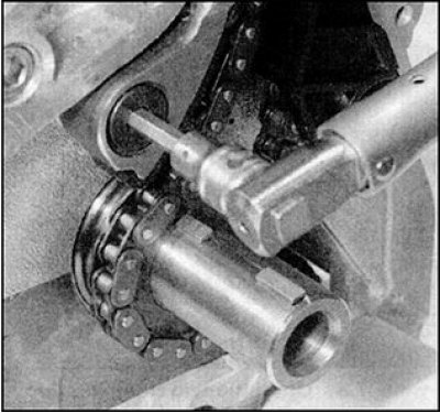
12. Install the chain tensioner shoe and tighten the shoe axle bolt to the specified torque.
13. Install the upper chain guide onto the cylinder head, tighten the bolts to the specified torque.
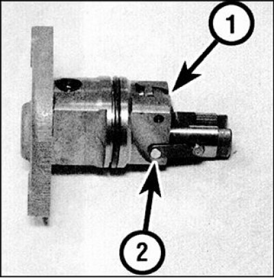
14. Release the tensioner lock lever (1), press the plunger into the housing and fix it in this position with the hook, placing it on the plunger pin (2).
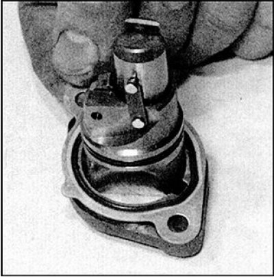
15. Install a new gasket on the tensioner flange and place a new sealing ring in the housing groove.
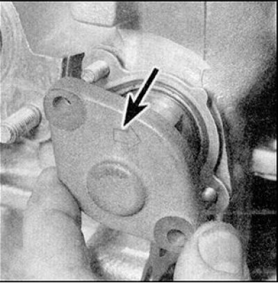
16. Install the tensioner, making sure the arrow on the flange points away from the cylinder head. Install the washers and tighten the tensioner nuts to the specified torque. Once the nuts are tightened, the mounting hook should automatically disengage from the pin, releasing the plunger.
17. Install a new oil filter and fill the engine with oil (see subsection 2.2.1).
18. Install the chain drive cover (see subsection 3.2.1.6).
19. Install the cylinder head cover (see subsection 3.2.1.4).