2. Due to the difference in the removal of injection and carburetor engines, the procedures are described separately, first for injection engines.
3. Remove the battery ground cable. The battery can be removed for more space. In addition, this prevents a short circuit during operation (e.g. if a tool is dropped on the terminals).
4. Unscrew the hood. Circle the hinges of the hood panel and unscrew the bolts. Ask an assistant to hold the hood so that it cannot tip over. Put the hood in a safe place so as not to damage it.
5. Remove all plates under the front of the car.
6. Remove the air filter as described in the appropriate section.
7. Drain the coolant as described in Chapter Cooling and heating systems. The coolant contains an antifreeze concentrate and must be collected in a clean container for reuse. To release, remove the lower hose on the radiator (after opening the lid).
8. Remove the radiator together with the fan, as described in Chapter Cooling and heating systems. In the case of an automatic transmission, also disconnect the oil cooler hoses from the radiator. Collect gear oil in a container underneath.
9. Remove the power steering pump without disconnecting the hoses. Remove the alternator and, if equipped, the A/C compressor. Do not disconnect compressor hoses from fittings.
10. Unscrew the muffler downpipe from the exhaust manifold and release the downpipe mount from the suspension. In Chapter Suspension and steering further guidance on this work is given.
11. Guided by the illustration, disconnect the shift bar (1) and thrust bar (2) with manual transmission installed.
In Chapter Manual transmission, differential and final drive further details of this work are given.
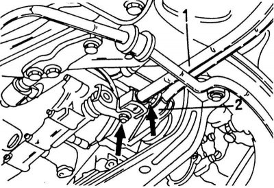
Disconnecting the shift rod with a manual gearbox installed
1 - switching rod
2 - thrust bar
12. With an automatic transmission installed, disconnect the shift cable on the gearbox side and the throttle cable on the engine side.
13. Loosen the nut inside the fork head (see illustration below) and disconnect the clutch cable from the release lever when it is long enough to do so.
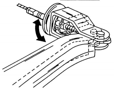
The clutch cable is held on the inside of the fork head.
14. Following the bend of the speedometer cable, remove the mounting plate bolt. Remove the entire clutch cable from the transmission. The drive gear remains on the cable. Plug the hole in the gearbox with a rag (see illustration below).
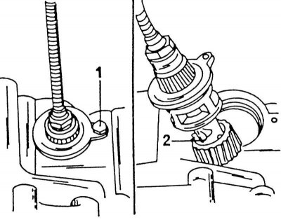
Fastening of a cable of a speedometer (1) on the left figure and pulling out the cable with the gear (2) on the right picture.
15. Disconnect the throttle cable from the throttle body.
16. Disconnect all vacuum and air hoses between the engine and a body. Depending on the country of destination and the laws in force regarding the regulation of the composition of exhaust gases, the routing of the vacuum hoses varies. Chapter Power supply and exhaust systems contains details on adjusting the composition of gases.
17. Disconnect all electrical wires between current consumers on the engine and the body. These include alternator, oil pressure sensor, remote thermometer thermal sensor, starter ignition distributor, etc.
18. Depressurize the system before shutting off the power system piping. To do this, open the lid of the fuse box and remove the fuse shown in the illustration. Start the engine. After a while, it will stall, as fuel will not be supplied. Turn the crankshaft again two or three times with the starter to relieve all pressure. Replace the fuse immediately. Now you can disconnect all the fuel hoses between the engine and the body.
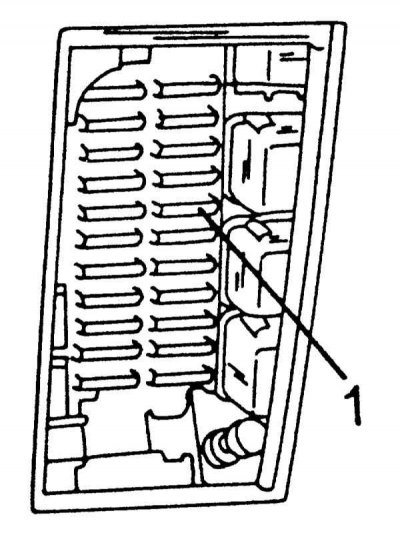
Fuel pump fuse position (1) in the fuse box.
19. Place the front of the car on supports and unscrew the front wheels.
20. Remove the brake calipers on both sides. At the same time, do not unscrew the brake hoses from the calipers and pipelines. After loosening the two bolts, hang the caliper on a wire from the front suspension so that the caliper does not hang from the hose.
21. On each side of the vehicle, unscrew the ball joint nut from the steering knuckle and disconnect the ball joint from the steering knuckle using a puller. Push the control arms down until the pivot pins are free. In the illustration, the lower arrow indicates the connection point of the ball joint. In chapter Front suspension the removal of the front suspension ball joint is described in detail.
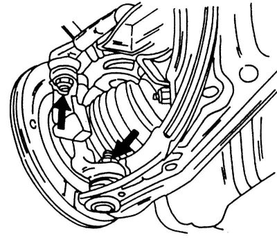
The arrows indicate the connections that need to be disassembled to remove the drive shafts.
22. Disconnect the tie rod ends in the same way, but this time from the steering lever. This connection is indicated in the illustration above with a left arrow. In Sections Steering without hydraulic booster and Power Steering (servo control) the use of the puller is described in more detail.
23. Drain gear oil.
24. Disconnect power shafts from a transmission as it is described in the Head Clutch and drive shafts and removing the steering knuckle, press the shafts outward from the gearbox. In this case, a screwdriver is installed behind the hinge. With a short jerk with a screwdriver, remove the retaining ring from the differential gear and the shaft will pop out. Depending on the version of the shaft, the removal may differ, which is described in more detail in Chapter Clutch and drive shafts. Do not damage the oil seal in the gearbox. If the oil seal is damaged, it must be replaced before installing the drive shaft.
25. Attach a suitable cable or chain to both engine lugs and tie the cable or chain to the crane. If there are no lifting eyes, you need to prepare two strong steel angles and screw one on the back, the other on the front of the cylinder head. Raise the unit slightly out of the engine compartment so that the cable is taut. Hold the engine and transmission in this position.
26. Place a mobile lift under the gearbox (placing a piece of wood between them) and lift up the gearbox. You may need to tighten the engine lift.
27. From the underside of a transmission unscrew and take out an average beam. It is fixed on both sides with two bolts and, in addition, is connected to the unit front and rear by suspension mounts.
28. Unscrew the one shown on the illustrations front engine mount and shown on illustrations rear engine mount. Also unscrew the gearbox mount. Always make sure that the weight of the unit is off the supports. Raise or lower the crane as required. When unscrewing the engine mount, follow some instructions:
- When loosening the suspension on the front side, remove only the bolt with nut inserted in the middle.
Front suspension injection engine.
- When loosening the rear engine mount, unscrew only the engine bracket from the cylinder block.
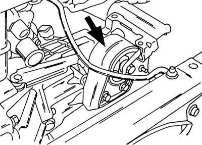
Rear engine mount. Injection and carburetor engine.
- The engine mounts remain on the engine and can be unscrewed if necessary after removing the unit.
29. Check that all connections between the machine and the body are loose and slowly lower the engine down. Operate the hoist and crane accordingly. An assistant is required to guide the machine. When lowering, take care not to damage engine parts, i.e. hoses, cables, lines, etc. Take care not to damage the brake pipes and brake master cylinder.
Removing the carburetor engine
1. Disconnect the ground cable from the battery. The battery should be removed to make more space. In addition, short circuits are prevented (e.g. if a tool is dropped on the terminals).
2. Unscrew the hood. Circle the hinges with a pencil and loosen the bolts. The assistant must hold the hood so that it does not tip over. Put the hood in a safe place so as not to damage it.
3. Remove all panels screwed under a forward part of a body.
4. Remove the air filter as described in the relevant chapter.
5. Drain the coolant as described in Chapter Cooling and heating systems. The coolant contains an antifreeze concentrate and must be collected in a clean container for reuse. To drain, disconnect the lower hose from the radiator (opening the radiator cap).
6. Remove the radiator together with the fan.
7. Unscrew the intake manifold supports to expose the battery cable connected to the starter.
8. Loosen the power steering pump belt and remove the pump without disconnecting the hoses.
9. Unscrew the muffler downpipe from the exhaust manifold and release the downpipe mount from the suspension.
In Chapter Suspension and steering detailed instructions for this work are given.
10. Guided illustration disconnect the shift bar (1) and thrust bar (2). In Chapter Manual transmission, differential and final drive this work is described in more detail.
11. Loosen the nut inside the fork head (see illustration) and disconnect the clutch cable from the release lever when it is long enough by loosening the nut.
12. Following the bend in the speedometer cable, remove the mounting plate bolt. Remove the entire clutch cable from the transmission. The drive gear remains on the cable. Plug the hole in the gearbox with a rag (see illustration).
13. Disconnect the throttle cable from the lever on the carburetor.
14. Disconnect all hoses and pipelines between the engine and the body.
15. Disconnect all electrical wires between consumers of energy on the engine and the body. These include alternator, oil pressure sensor, remote thermometer thermal sensor, starter ignition distributor, etc.
16. Disconnect the fuel lines between the fuel pump and the pipeline from the tank.
17. Put the front of the car on supports and unscrew the front wheels.
18. Remove the brake calipers on both sides. At the same time, do not unscrew the brake hoses from the calipers and pipelines. After loosening the two bolts, hang the caliper on a wire from the front suspension so that the caliper does not hang from the hose.
19. On each side of the vehicle, unscrew the ball joint nut from the steering knuckle and disconnect the ball joint from the steering knuckle using a puller. Push the transverse arm down until the pivot pins are free. On illustrations the lower arrow indicates the connection point of the ball joint. In chapter Front suspension the removal of the front suspension ball joint is described in detail.
20. Disconnect the tie rod ends in the same way, but this time from the steering lever. This connection is marked on illustrations Steering without hydraulic booster and Power Steering (servo control) the use of the puller is described in more detail.
21. Drain gear oil.
22. Disconnect power shafts from a transmission as it is described in the Head Clutch and drive shafts and removing the steering knuckle, press the shafts outward from the gearbox. In this case, a screwdriver is installed behind the hinge. With a short jerk with a screwdriver, remove the retaining ring from the differential gear and the shaft will pop out. Depending on the version of the shaft, the removal may differ, which is described in more detail in Chapter Clutch and drive shafts. Do not damage the oil seal in the gearbox. If the oil seal is damaged, it must be replaced before installing the drive shaft.
23. Attach a suitable cable or chain to both engine lugs and tie the cable or chain to the crane. If there are no lifting eyes, you need to prepare two strong steel angles and screw one on the back, the other on the front of the cylinder head. Lift the unit slightly out of the engine compartment so that it is slightly taut. Hold the engine and transmission in this position.
24. Substitute a mobile lift under the gearbox (placing a piece of wood between them) and lift up the gearbox. You may need to tighten the engine lift.
25. From the underside of a transmission unscrew and take out an average beam. It is fixed on both sides with two bolts and, in addition, is connected to the unit front and rear by suspension mounts.
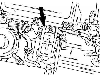
26. Unscrew the front engine mount shown in the illustration.
Engine mount on the front side of the carburetor engine. The arrows indicate where the bolts are.
27. To do this, unscrew only the three bolts indicated by arrows.
28. Unscrew the one shown on the illustrations rear engine mount. Also unscrew the gearbox mount. Always make sure that the weight of the unit is off the supports. Lower or raise lift as needed.
29. Check that all connections between the machine and the body are loose and slowly lower the engine down. Operate the hoist and crane accordingly. An assistant is required to guide the machine. When lowering, be careful not to damage engine parts, i.e. hoses, cables, pipes, etc. Be careful not to damage the brake pipes and brake master cylinder.
Unit installation
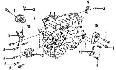
Elements mounted on a carburetor engine
1 - 45-55 Nm; 2 - 50-60 Nm; 3 - 22-29 Nm; 4 - front engine support; 5 - front engine mounting bracket; 6 - rear engine support; 7 - eyes for lifting
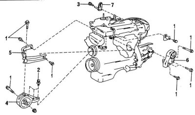
Elements installed on the injection engine
1 - 45-55 Nm; 2 - 50-60 Nm; 3 - 22-29 Nm; 4 - 74-83 Nm; 5 - 64-74 Nm; 6 - 62-78 Nm; 7 - front engine support; 8 - suspension carrier; 9 - rear lifting eye; 10 - rear engine mount; 11 - front lifting eye
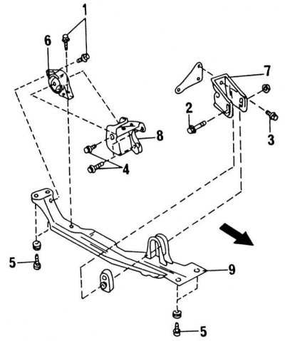
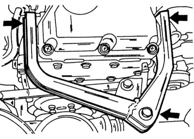
Engine suspension elements mounted on the transverse beam. The arrow points to the front of the car
1 - 50-60 Nm; 2 - 62-78 Nm; 3 - 45-55 Nm; 4 - 65-75 Nm; 5 - 77-98 Nm; 6 - rear engine support; 7 - suspension console; 8 - suspension console; 9 - cross beam
1. Place the engine and transmission under the vehicle and attach the cable to the eyelets. Lift the unit on a cable into the engine compartment until it is approximately in the required position. Check that there are no disabled elements in the path. When lifting, be careful not to flatten any elements. Make sure that the brake lines and master cylinder are not damaged.
2. Align the engine in the mounts and set the cable tension so that the engine mounts can be secured. When screwing the engine mounts, follow these instructions:
- Tighten the nuts and bolts of the front engine mount, i.e., shown in the illustrations Rear engine mount. Injection and carburetor engine or Engine mount on the front side of the carburetor engine, with a force of 45-55 Nm. If the engine mount has been unscrewed from the console (injection engine) or from the engine (carbureted engine), it should be screwed with a force of 50-60 Nm.
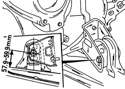
The height of the engine mount on the cross member must match the specified dimension. Only then tighten the horizontally inserted bolt with nut.
3. Torque the horizontally inserted bolts to 45 - 55 Nm.
- Tighten the bolts and bolts of the rear suspension of the unit with a force of 45 - 55 Nm. Tighten the large through bolt with the same torque.
- With a manual gearbox installed, the engine mount shown in the illustration above must be adjusted in height. The suspension console has longitudinal holes and the inserted bolt should be tightened with a nut with a force of 62 - 78 Nm when the one shown on illustrations size.
- Tighten the cross beam on the underside at both ends to 77 - 98 Nm. If the rear support has been removed, tighten it with a force of 50 - 60 Nm. If the bracket on the other side of the engine has been unscrewed, it should be tightened with a force of 45 - 55 Nm.
- All other engine mount tightening torques are shown in the illustrations Elements installed on the injection engine and Engine suspension elements mounted on the transverse beam. The arrow points to the front of the car Since the tightening torques are very different from each other, you should be very careful not to break the bolt.
4. Disconnect the cable from the power unit and remove the lift.
5. Insert power shafts into a transmission as it is described in the Head Clutch and drive shafts.
6. Connect all electrical wires between electrical consumers on the engine and body. These include the alternator, oil pressure sensor, remote thermometer heat sensor, starter ignition distributor, power system parts, etc. Reconnect the fuel lines.
7. Connect all vacuum and air hoses between the engine and a body. Depending on the country of destination and applicable laws on the regulation of the composition of exhaust gases, the routing of the vacuum hoses differs. In Chapter Power supply and exhaust systems details on the adjustment of the composition of the exhaust gases are given.
8. Connect the gas cable in place and check that the throttle valve opens fully when the gas pedal is depressed.
9. Insert the speedometer cable and install the mounting plate shown in illustrations. Tighten the fixing plate bolts.
10. Attach the clutch cable to the engagement lever and tighten the adjusting nut. Adjust the clutch pedal as described in Chapter Clutch and drive shafts and tighten the locknut.
11. With an automatic transmission installed, connect the shift cable and throttle cable to the box.
12. Guided illustration, attach shift bar (1) and thrust bar (2), if a manual transmission is installed. In Chapter Manual transmission, differential and final drive a detailed description of this work is given.
13. Screw the exhaust pipe of the muffler to the exhaust manifold and fix the pipe in the suspension. This work is described in detail in Chapter Suspension and steering.
14. Install the power steering pump, if any.
15. Establish a radiator as it is described in the Head Cooling and heating systems. If an automatic transmission is installed, connect an oil cooler to the radiator. Check the transmission oil level, top up if necessary.
16. Fill in a cooling liquid as it is described in the Head Cooling and heating systems.
17. Install the air filter and connect the suction hoses.
18. Screw on the hood. The hinge marks must match. Apply the hood with the help of an assistant so that it cannot tip over.
19. Start and warm up the engine. Check ignition timing and engine idle, adjust if necessary.
Detaching and attaching the gearbox
1. Unscrew the starter from the clutch housing.
2. Loosen the bolts between the engine and gearbox.
3. Disconnect the box from the engine. Make sure that the weight of the gearbox does not act on the clutch shaft. Attaching the gearbox is carried out in reverse order.
Engine mounts
As mentioned in the previous chapter, injection engine mounts are different from carbureted engine mounts. To avoid mistakes when tightening the bolts, follow the illustrations. Mounting bracket marked (7) on illustrations, bolted to the engine. The console has longitudinal holes that serve to adjust the engine mount in height. Rear support (6) screwed onto the crossbeam and held inside the carrier (8).