Removing
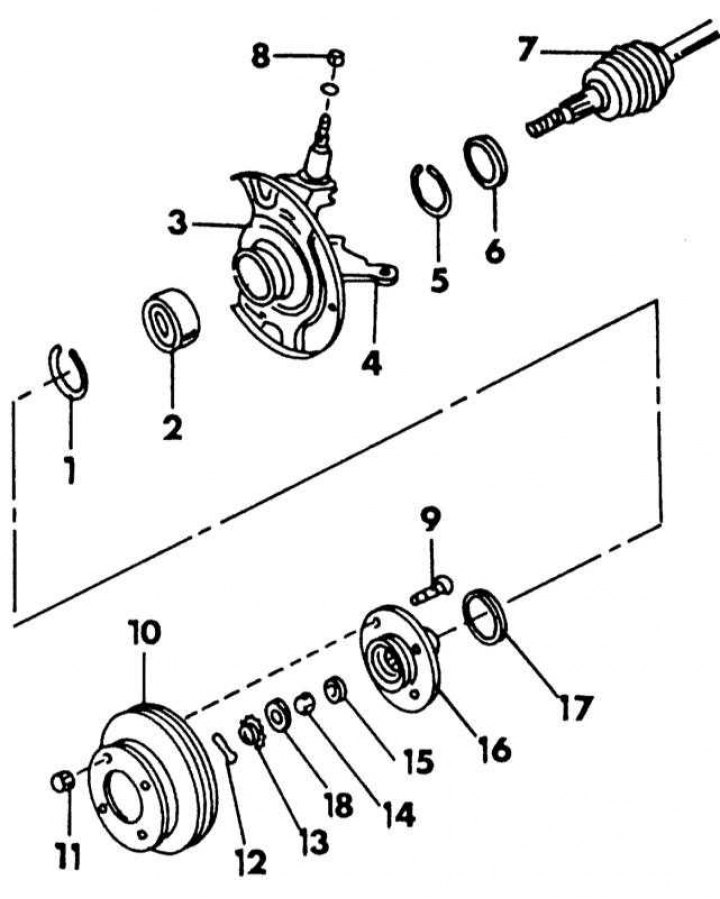
Disassembled view of steering knuckle with hub bearing and drive shaft
1 - retaining ring, external; 2 - hub bearing; 3 - shield; 4 - rotary fist; 5 - retaining ring, internal; 6 - inner gland; 7 - drive shaft; 8 - nut, 100-120 Nm; 9 - wheel pin; 10 - brake disc; 11 - wheel bolt, 100-120 Nm; 12 - cotter pin; 13 - nut retainer; 14 - hub bearing nut, 240-320 N·m; 15 - washer; 16 - wheel hub; 17 - external gland; 18 - intermediate washer
Removing the hub and steering knuckle is also recommended if the driveshaft needs to be removed, whether for repair, transmission removal, or other work.
1. Loosen the wheel nuts and driveshaft nut while the vehicle is on wheels.
2. Place the front of the car on stands and remove the wheel.
3. Remove the brake caliper. To do this, remove both of the bolts shown in the illustration below. Tie the brake caliper with a piece of wire to the front suspension. Do not allow the caliper to sag on the hose.
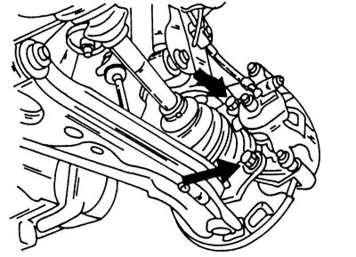
Both bolts, shown by arrows, hold the brake caliper.
4. Remove the cotter pin from the castle nut of the steering rod, loosen the nut and separate the joint with a suitable puller from the steering arm (see illustration below). In order not to damage the threads, you can screw the inverted nut onto the pin so that it is flush with it.
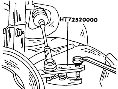
Pressing the tie rod ball pin out of the tie rod lever using a special puller.
5. Loosen the nut on the upper side of the steering knuckle and remove the steering knuckle guide pin from engagement with the upper arm. As you can see, the connections are different from previous Nissan models. Press the entire steering knuckle down until it reaches the position shown in the illustration below.
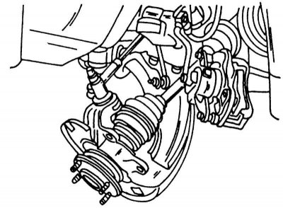
Tilt the steering knuckle assembly down and then knock the clamp out of the hub.
6. Thread the nut onto the drive shaft until the outside is flush with the shaft and tap the shaft in slightly with an alloy hammer to loosen it from the hub bearing.
7. On the underside of the steering knuckle, remove the ball joint nut on the transverse arm and separate the ball joint connection with a puller. The puller shown in the illustration below is also suitable for suspension ball joints.
Checking the fluid level in the compensation tank of the servo control.
1 - warm; 2 - cold
7. Take out a rotary fist from a forward suspension bracket. Remove the brake disc.
8. If the steering knuckle needs to be removed together with the drive shaft, drain the gear oil (unscrew the plug and substitute the container).
9. Squeeze out power shafts from a transmission as it is described in the Head Clutch and drive shafts for left and right shafts, as well as for manual or automatic transmission.
10. Remove the hub, steering knuckle and drive shaft from the vehicle or leave the drive shaft in the gearbox and remove the steering knuckle with hub from the drive shaft.
Disassembly and replacement of the wheel bearing
1. Completely unscrew the hub nut and remove the drive shaft from the hub if it is still installed.
2. Clamp the steering knuckle in a vise and knock out the hub with an alloy rod from the back. If the hub is knocked out of the steering knuckle, the hub bearing must always be replaced. The inner race of the bearing remains on the hub and must be removed with a suitable puller.
3. Remove the retaining ring on the outside of the steering knuckle with special pliers. On the reverse side, remove the oil seal with a screwdriver and remove the second circlip. The serrations in the retaining ring facilitate the installation of the pliers.
4. Put the steering knuckle under the press and press out the hub bearing from the outside to the inside. Use a piece of pipe to press out the bearing. Thoroughly clean all parts. Bearings should always be replaced along with the races, as they run in to each other. The steering knuckle can only be checked with a magnetic tool.
Steering knuckle assembly
When installing the hub bearing and assembling the steering knuckle, proceed as follows:
1. Thoroughly clean the grease from the steering knuckle hole and the outer side of the hub bearing, and insert the inner retaining ring into the steering knuckle groove.
2. Press the new bearing from the outside into the steering knuckle until it rests against the circlip. When doing this, apply force to the outer race of the hub bearing.
3. Insert the outer retaining ring into the groove. Check that the circlip fits perfectly around its entire circumference.
4. Lubricate the working edges of both oil seals with grease and hammer in front and rear into the steering knuckle without damaging them. Wipe off excess lubricant.
5. Place the steering knuckle on the press table and press the hub into the bearing and steering knuckle. Be sure to ensure that the pressing pressure does not exceed 3 tons.
6. Now you should check the bearing preload. To do this, put the steering knuckle on the press table and increase the load on the outer side of the hub to 3.5 -5.0 tons. While holding the load, move the steering knuckle from side to side several times. The steering knuckle should turn without sticking, despite the load.
Installing the steering knuckle
Installing the steering knuckle with the drive shaft is carried out in the reverse order. Always install a new circlip on the end of the drive shaft. Details on installation of power shafts are given in the Chapter Clutch and drive shafts. When installing the drive shafts in the differential, align the spline well. After installation, pull on the shaft to check that the ring has snapped into place.
You must comply with all of the Specifications at the beginning of the chapter tightening torques. Tighten the drive shaft nut with a force of 240-320 Nm, install a retainer on the nut and insert a new cotter pin.