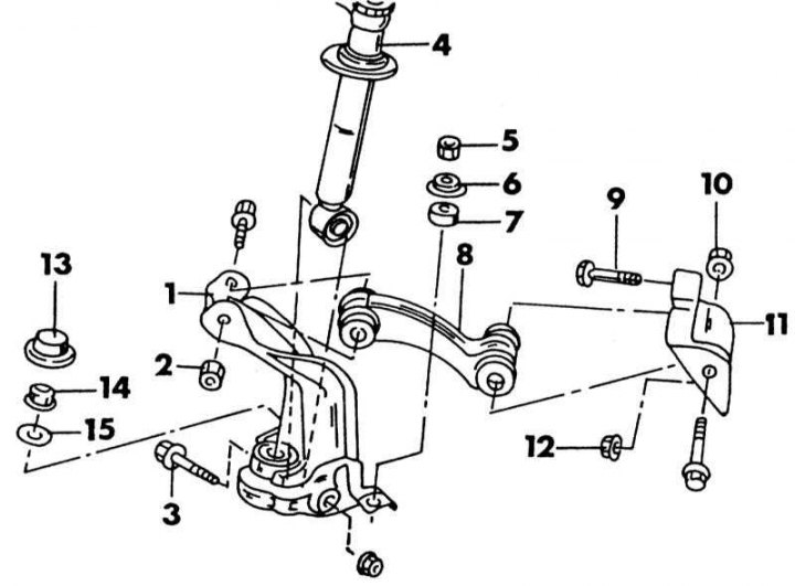
Top wishbone mounting
1 - ball bearing; 2 - nut, 112-126 Nm; 3 - suspension strut bolt, 112-126 Nm; 4 - shock absorber; 5 - nut, 16-22 Nm; 6 - cup; 7 - rubber bushing; 8 - upper transverse lever; 9 - bolt, 90-125 Nm; 10 - nut, 90-125 Nm; 11 - transverse arm console; 12 - nut, 90-125 Nm; 13 - cap; 14 - nut, 100-120 Nm; 15 - puck
The illustration above shows the unusual arrangement of a multi-link wheel suspension consisting of a lower wishbone (see Section Lower wishbones), as well as a diagonal upper transverse arm with a hinge. The upper wishbone is located between the body and the upper ball joint. The lower part of the suspension strut is fixed in the ball joint and on the lower side is the support pin of the steering knuckle. This joint contains a bearing which is capped but does not normally require maintenance. The bearing can be replaced.
On a vehicle with an injection engine, the anti-roll bar connecting rod is connected to the hinge. On a car with a carburetor engine, the rod is connected to the transverse arm.
The wishbone can be easily removed as there is no need to remove the suspension strut from the vehicle. It should be noted that all parts resting on rubber bushings should be tightened when the vehicle rests on the wheels.
1. Raise the front of the car.
2. Place a lift under the lower transverse arm.
3. Loosen the nut and bolt on the underside of the shock absorber and knock out the bolt.
4. With the injection engine installed, remove the stabilizer connecting rod nut, remove the parts under it, and remove the rod.
5. Remove the knuckle swivel cap and remove the support pin nut underneath on the underside of the ball joint.
6. Unscrew the upper cross arm on the inside and outside.
7. Set the lift to the best position and remove the parts that are required. When observing the upper transverse arm, you will notice that the steering arm on the left side is marked "L", and on the right side the notation "R". The control arm bushings cannot be replaced. Both swivel bearings on the steering knuckle can be replaced. To do this, knock out both bearings from opposite sides of the hinge. The lower bearing is sealed with an oil seal. The outer bearing races remain in the hinge, which should be knocked out from opposite sides. To do this, the rod should be installed in the groove of the corresponding holder. The top bearing should be pressed in to 2.5mm from the top surface of the bearing to the top edge of the pivot housing. Finally, hammer in the gland again until it is flush.
8. Installation of the upper transverse arm and hinge is carried out in the reverse order of removal. Fasten all parts without tightening, and when the wheels are on the ground, tighten the bolts and nuts as shown on illustrations effort. Pay attention to the designations L and R when installing the upper transverse arm. Fill the knuckle bearing housing and cap with grease, tighten the nut and fit the cap. The illustration below shows arrows for tightened connections (connection of the anti-roll bar only in case of installed injection engine).
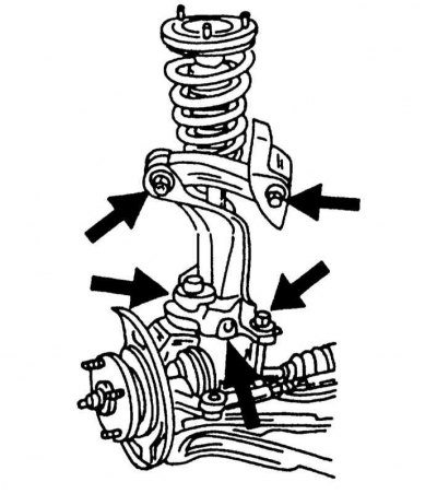
The arrows show the mounting points of the upper transverse arm and the ball joint of the steering knuckle. On a model with an injection engine, you can also see the connection of the anti-roll bar.