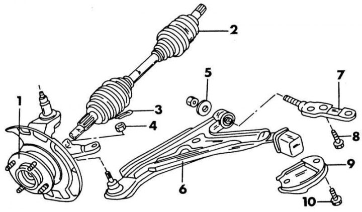
Details of the lower transverse arm and its fastenings
1 - knuckle with hub; 2 - drive shaft; 3 - cotter pin; 4 - nut, 72-88 Nm; 5 - nut and washer, 95-120 Nm; 6 - lower transverse lever; 7 - support shaft; 8 - bolt, 120-150 Nm; 9 - mounting clamp; 10 - bolt, 120-150 Nm
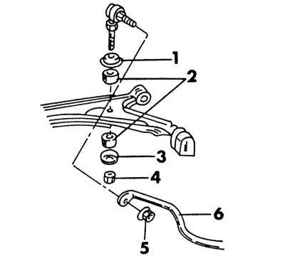
Mounting the anti-roll bar on a carburetor model
1 - cup; 2 - rubber bushing; 3 - cup; 4 - nut, 19-25 Nm; 5 - nut, 41-50 Nm; 6 - anti-roll bar
The mounting of the lower transverse arms is shown in illustrations. The illustration shows the transverse arm fitted on a model with an injection engine. On the model with a carburetor engine, the anti-roll bar is connected at the upper end to the transverse arm by means of a ball-joint rod. This design is shown in illustrations.
When removing the transverse arm, proceed as follows:
1. Put the front of the car on stands.
2. Disconnect the stabilizer link. On a fuel-injected engine, the stabilizer only passes through the wishbone and must be loosened at the steering knuckle; on a carbureted model, unscrew the swivel from the end of the stabilizer bar.
3. Remove the steering knuckle ball nut on the inside and squeeze out the ball pin. The puller used to remove the tie rod end is suitable for this job.
4. Now unscrew the transverse arm inside. To do this, remove both screws inserted from below (10) (see illustration) and loosen the nut and washer (5) on the opposite side. Pull the control arm back until it is free from the support pin and remove it. If required, the support shaft can be removed (7) for transverse link after removing bolts (8). The illustration below shows where the transverse arm is attached.
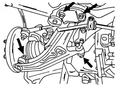
Arrows indicate where to loosen connections to remove transverse arm.
5. Transverse arm bushings cannot be replaced. If damaged, replace the entire lever. The same applies to a broken ball joint. If it has axial play (up and down), the control arm should be replaced. A hinge that has lost its mobility also requires replacement of the transverse arm.
6. Installation of the transverse lever is carried out in the reverse order. The required tightening torques are shown on illustrations. tighten the nut (5) and bolts (10), when the car will stand with its wheels on the ground, while the car should not be additionally loaded. Lubricate the bearing points with a small amount of grease. After installing the parts, check the wheel alignment. Wheel alignment may need to be adjusted.
The following instructions must be observed:
7. Slide the transverse arm on one side of the support shaft trunnion, fit the washer and hand tighten the nut.
8. On the other side, fix the mounting clamp (9) with bolts (10). Screw in both bolts without tightening.
9. Connect the transverse arm ball pin to the steering knuckle and tighten the castle nut to 72 - 88 Nm. Insert new pin. Tighten the nut a little if the cotter pin does not fit.
10. Insert the anti-roll bar connecting rod through the transverse arm and attach the anti-roll bar as described in the next chapter.
11. Lower the car on wheels.
12. Tighten the transverse arm nut to the specified illustrations locations with the appropriate tightening torque. This ensures that the bushings are properly tightened. All other points are indicated in the illustrations already given.