When measuring camber and runout, the vehicle must be brought into working condition. In addition, the fuel tank must be filled.
Adjustment values are given in Specifications at the beginning of the chapter.
Toe adjustment
Toe-in is adjusted after loosening the tie rod lock nuts by lengthening or shortening the tie rod. The tie rods are left hand threaded on one side and right hand threaded on the other so that the middle tube can be rotated left or right to change the alignment (illustration below).
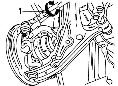
Tie rod offset. Loosen locknut first (1).
If the tie rods were removed, they must be set at a distance of 183.6 mm before starting the toe adjustment. The distance is measured between the arrows (see illustration below).
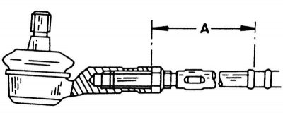
Size "A" between the steering rods must be adjusted to the specified value.
Proceed as follows when measuring toe-in:
1. Attach a suitable template to the front of the wheels and set the scale to "0". Mark the contact surface with chalk.
2. Move the car half a wheel turn forward until the chalk marks are at the rear.
3. Apply installed on "0" template to the rear of the wheels and move the feeler gauge. Read the size on the instrument scale.
4. If the size on the back is larger than on the front and lies within the limits specified in Specifications at the beginning of the Chapter, the adjustment is correct. Keep in mind that convergence can be negative (up to -0.5 mm), without the need for further adjustment.
5. Loosen the lock nuts to correct the adjustment (see illustration) both tie rods and move both tie rods by the same amount with a wrench. Re-measure the toe and tighten the locknuts to 37-46 Nm.
Overrun test (longitudinal tilt of the axis of rotation)
The overrun can be measured with a conventional protractor designed for this purpose. Of course, optical instruments are more accurate. The run-out angle is understood as the tilt of the steering knuckle back, relative to a line drawn upward at right angles to the road surface, looking from the side at the wheel and suspension strut. If you imagine a line drawn through the suspension strut, it should pass in front of the front wheel onto the road. The illustration below shows the run-out angle.
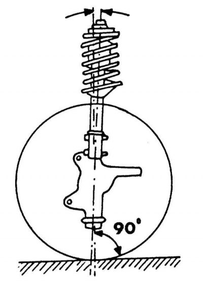
Image of the coast. The arrow shows the direction of movement.
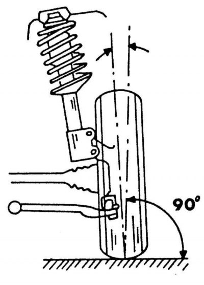
Image of the camber angle. Camber is measured between arrows.
The overrun value is given in Specifications at the beginning of the chapter.
If the measurement reveals that the runout is out of tolerance, the front suspension should be checked for deformation. For example, a sharp ride on a curb can have a negative impact on coastdown.
Camber check and adjustment
Camber is understood as the angle of inclination of the steering knuckle outward, when looking at the front side of the wheel, relative to a line drawn perpendicular to the road. On illustrations the camber angle is clearly shown. The camber angle can be measured with a conventional camber gauge, but optical instruments are of course more accurate. Camber angle is measured in degrees and minutes.
If the measurement reveals that the camber angle is out of tolerance, it can be assumed that one or more elements of the front suspension are deformed. Check it.
Wheel Angle Adjustment
To fine-tune the steering angle, the front wheels should be mounted on a turntable. The steering angle is specified in Specifications. As can be seen, the steering angles of the inner steer wheel and the outer steer wheel are different. In addition, there is the so-called difference toe angle, in which one wheel is offset by an angle of 20°. Only when driving over rough terrain can the steering angle of the wheels change. It is best to measure it in the workshop.