


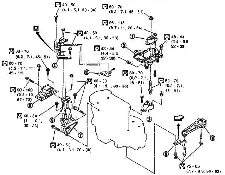
1. Left engine mount insulator; 2. Left engine support bracket (from the car side); 3. Left engine support bracket (from the gearbox side); 4. Right engine support stand (the shape may differ from the one shown in the picture); 5. Right engine mount insulator; 6. Right engine support bracket (upper); 7. Right engine support bracket (lower); 8. Rear engine mount bracket; 9. Rear reaction rod; 10. Rear engine mounting bracket
Attention:
- Stop the vehicle on a level, firm surface.
- Place chocks under the rear wheels at the front and rear.
- If the engine is not equipped with lifting eyes, select them and bolts from the parts catalog.
- Always carry out work in safe conditions, avoid performing unintended operations.
- Do not begin work until the exhaust system and engine coolant have cooled sufficiently.
- If the required components or operations are not covered in the chapter Mechanical part of the engine, see the relevant chapters.
- Always lift the engine using the indicated points.
- Use either a 2-post lift or other independent lift available to you. If, for reasons beyond your control, you have to use a side stand, before starting work, support the car at the support point on the rear axle with a telescopic stand or similar device to prevent the center of gravity from shifting to the rear.
- For the support points for the lift and jack on the rear axle, see chapter General information and maintenance, "Garage jack, safety stands and 2-post lift".
Removal
Description of works
Remove the engine and transmission from the vehicle and separate the engine and transmission.
Preparatory work
1. If the engine can be supported by a winch, remove the hood.
2. Relieve the fuel pressure. See chapter Engine management system.
3. Drain the engine coolant. See chapter Engine lubrication and cooling systems.
4. Remove the following components:
- front wheels;
- protective strip from the front right and left fenders;
- front exhaust pipe; see chapter Accelerator fuel system and exhaust system;
- drive belts; see above section "Drive belts";
- air duct; see above section "Air purifier and air duct";
- battery;
- radiator; see chapter Engine lubrication and cooling systems.
In the engine compartment on the left
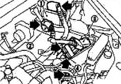
5. Disconnect the connectors and terminals from the following components:
Note: Remove the ECM (1) from the bracket and disconnect the two wiring connectors.
Caution: Do not strike the ECM.
Disconnect the intermediate connector (2) of the main electrical wiring between the vehicle and the engine compartment ECM sub-unit.
Disconnect the connectors from the positive battery terminal (3).
Disconnect the ground wire from the gearbox side (4).
6. Disconnect the heater hose. Plug the hose to prevent engine coolant from leaking.
7. Disconnect the gear shift cable from the gearbox. See chapter Manual transmission.
8. Disconnect the clutch pipe from the gearbox side and temporarily secure it to the vehicle.
Install a plug to prevent fluid from leaking out of the clutch.
9. Remove the crankshaft angle sensor (POS) from the transmission.
Caution: Handle the sensor with care, do not drop or hit it.
In the engine compartment, front and right
10. Disconnect the ground wire between the generator bracket and the vehicle.
11. Remove the right engine mount stand, generator bracket and generator.
12. Remove the air conditioning compressor with the pipes connected from the engine and temporarily secure it to the car with a rope to prevent stretching the pipes.
13. Remove the fuel pipe protective cover. See section "Fuel injectors and fuel line".
14. Disconnect the fuel hose. Plug the hose to prevent fuel from leaking.
Under the bottom of the car
15. Remove the ABS wheel sensor from the steering knuckle.
16. Remove the brake caliper from the steering knuckle. Temporarily secure the caliper to the side of the vehicle with a rope, etc. to prevent stretching the brake hose. See Chapter Brake system.
17. Remove the right and left drive shafts. See chapter Front axle and suspension.
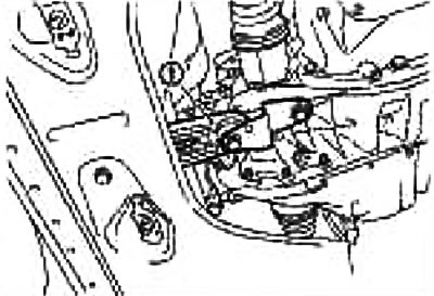
18. Remove the rear reaction rod (1).
Removal operations
19. Secure the engine lifting eyes at the front left of the cylinder head (1) and at the rear right of the cylinder head (2) and hang the engine on a winch.
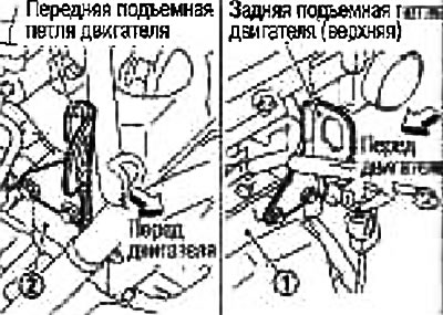
Note: Use the stock hinges on the front and back sides.
Tightening torque: 16.6-23.5 N·m (1.7-2.3 kg·m)
From the front side, remove the wiring bracket under the fuel pipe protective cover and secure it in the bracket mounting hole. See section "Fuel injectors and fuel line".
20. Raise the winch to a height that is comfortable for operation, support the bottom of the engine or use a trolley with a lifting table (suitable special tool), or two safety stands and adjust the winch tension.
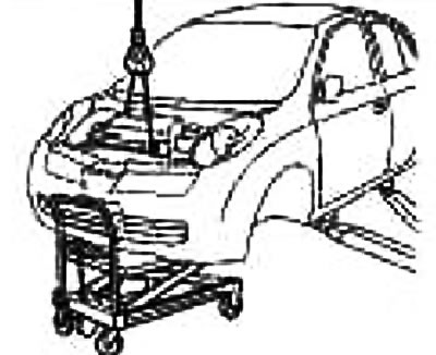
Caution: Place a piece of board or similar as a support surface for stability. Make sure that the hanging chain or lifting hook does not come into contact with the air conditioning pipes or the car (hood grille). Also make sure that they will not interfere with the work being carried out.
21. Unscrew the mounting bolts (2) of the right engine support bracket (upper) (1).
22. Unscrew the nut (3) from the bolt of the left engine support.
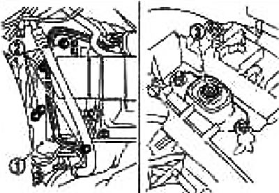
23. Carefully lower the lift table trolley or suitable jack (or raise the lift) and remove the engine and gearbox from the vehicle.
If you are going to lower the engine side, do this operation in sync with the winch.
Attention:
- Make sure that no part of the engine touches the body.
- Make sure all pipes, wiring, etc. are disconnected.
- Make sure that the hanging chain or lifting hook does not come into contact with the air conditioning pipes or the vehicle (hood grille).
- When removing the engine and transmission assembly, do not allow the vehicle to fall off the lifting device due to a shift in the center of gravity.
- If necessary, support the vehicle using a jack or equivalent device from behind.
Separation operations
Separate the engine and gearbox on a level surface as follows:
Caution: During this operation, support the engine securely by placing a block of wood under the engine oil pan, transmission oil pan and suspension beam and hang it by the lifting eyes using a winch.
24. Remove the generator. See chapter Electrical equipment.
25. Separate the engine from the gearbox. See chapter Manual transmission.
Installation
Installation is carried out in the reverse order of removal, taking into account the following:
- Avoid damaging the engine mount insulator or allowing oil to come into contact with it.
- If installation direction is specified, refer to the component drawing above.
- Make sure all support insulators are seated correctly and tighten the mounting nuts and bolts.
Post-installation check
Before starting the engine, check the level of coolant, engine oil and working fluids. If the level is below normal, top up and bring to the required level.
Check for fuel leaks as follows:
- Turn the ignition key to the "ON" position (without starting the engine). After creating pressure in the fuel lines, check for fuel leaks at the joints.
- Start the engine. While increasing the engine speed, check again for fuel leaks at the fuel line joints.
Let the engine run and check for any unusual noise or vibration.
Warm up the engine thoroughly and make sure there are no coolant, engine oil, working fluids, fuel or exhaust leaks.
Bleed air from the pipes and hoses of the relevant systems, such as the cooling system.
After the engine has cooled down, check the coolant, engine oil and working fluid levels again. If necessary, top up and bring to the required level.