


Car glass and mirrors Nissan Note 1

Windshield — Removal and Installation
1. Windshield molding; 2. Windshield; 3. Clamp; 4. Rubber partition; 5. Sealant; 6. Primer; 7. Mirror base; 8. External roof panel; 9. Outer body panel; 10. Rain sensor...
1. Windshield molding; 2. Windshield; 3. Clamp; 4. Rubber partition; 5. Sealant; 6. Primer; 7. Mirror base; 8. External roof panel; 9. Outer body panel; 10. Rain sensor...

Side window glass — removal and installation
1. Side window glass; 2. Sealant; 3. Primer; 4. Outer body panel; 5. Spacer; 6. Clamp Removal 1. Remove the rear pillar trim. 2. To avoid damage to painted surfaces,...
1. Side window glass; 2. Sealant; 3. Primer; 4. Outer body panel; 5. Spacer; 6. Clamp Removal 1. Remove the rear pillar trim. 2. To avoid damage to painted surfaces,...

Rear Door Window Glass — Removal and Installation
1. Rear door window glass molding; 2. Rear door window glass; 3. Clamp; 4. Spacer; 5. Sealant; 6. Primer; 7. Rear door outer panel Removal 1. Remove the trim from the...
1. Rear door window glass molding; 2. Rear door window glass; 3. Clamp; 4. Spacer; 5. Sealant; 6. Primer; 7. Rear door outer panel Removal 1. Remove the trim from the...

Rear Window Defogger — Component and Connector Locations
1. VSM block (body control unit). M57, M59. 2. Rear window defroster switch (built into the air conditioner amplifier).M64, M65 (on models with automatic air...
1. VSM block (body control unit). M57, M59. 2. Rear window defroster switch (built into the air conditioner amplifier).M64, M65 (on models with automatic air...
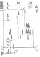

Rear window defroster — standard voltage values at the contacts of the BCM unit
Contact No Wire color Component Input/Output signal State Voltage (V) (approx.) 2 Black Weight - - 0 4 White Signal to rear window defroster switch Entrance When the...
Contact No Wire color Component Input/Output signal State Voltage (V) (approx.) 2 Black Weight - - 0 4 White Signal to rear window defroster switch Entrance When the...
Rear Window Defogger — IPDM E/R Unit Terminal Voltage Standard Values
Contact No Wire color Component Input/Output signal State Voltage (V) (approx.) 3 Black Weight (power supply) - - 0 8 Red Output signal to rear window heater relay exit...
Contact No Wire color Component Input/Output signal State Voltage (V) (approx.) 3 Black Weight (power supply) - - 0 8 Red Output signal to rear window heater relay exit...

Rear Window Defogger — Checking the Defogger Wire
1. When measuring voltage, wrap the tip of the negative probe with tin foil. Then press the foil onto the wire with your finger. 2. Connect the tester probes (in the...
1. When measuring voltage, wrap the tip of the negative probe with tin foil. Then press the foil onto the wire with your finger. 2. Connect the tester probes (in the...

Rear Window Defogger — Defogger Wire Repair
Repair accessories Conductive silver paint (Dupont No 4817 or equivalent) Ruler 30 cm long Drawing pen Fan heater Alcohol Rag Procedure for carrying out repairs 1. Clean...
Repair accessories Conductive silver paint (Dupont No 4817 or equivalent) Ruler 30 cm long Drawing pen Fan heater Alcohol Rag Procedure for carrying out repairs 1. Clean...

Power windows — component and connector locations
1. VSM block (body control unit). M57, M59 (view with the top section of the dashboard removed). 2. Main window switch D8, D9. 3. Rear right side door window switch D63....
1. VSM block (body control unit). M57, M59 (view with the top section of the dashboard removed). 2. Main window switch D8, D9. 3. Rear right side door window switch D63....
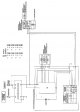
Electric windows — wiring diagram
Models with front window lifts Models with front and rear side door power windows
Models with front window lifts Models with front and rear side door power windows
Electric windows — standard voltage values at the contacts of the VSM unit
Contact No Wire color Component Input/output signal State Voltage (V) (approx.) 2 Black Weight - Ignition key in the "ON" position 0 24 Ignition key (in the "ON" or...
Contact No Wire color Component Input/output signal State Voltage (V) (approx.) 2 Black Weight - Ignition key in the "ON" position 0 24 Ignition key (in the "ON" or...

Front door glass and window lifter — removal and installation
1. Door handle bracket; 2. Inner lining; 3. Door glass; 4. Lower guide (rear); 5. Window lifter assembly; 6. Window lift motor; 7. Door glass guide channel; 8. Lower...
1. Door handle bracket; 2. Inner lining; 3. Door glass; 4. Lower guide (rear); 5. Window lifter assembly; 6. Window lift motor; 7. Door glass guide channel; 8. Lower...

Rear side door glass and window lifter — removal and installation
1. Door handle bracket; 2. Corner inner cover; 3. Lower guide (rear); 4. Door glass; 5. Window lifter assembly; 6. Window lift motor; 7. Door glass guide channel; 8....
1. Door handle bracket; 2. Corner inner cover; 3. Lower guide (rear); 4. Door glass; 5. Window lifter assembly; 6. Window lift motor; 7. Door glass guide channel; 8....

Door mirrors — removal and installation
1. Corner cover; 2. Door mirror assembly Caution: Do not damage the door mirror housing. Removal 1. Remove the front door trim. See section " Exterior finishing ". 2....
1. Corner cover; 2. Door mirror assembly Caution: Do not damage the door mirror housing. Removal 1. Remove the front door trim. See section " Exterior finishing ". 2....

Door mirrors — disassembly and assembly
1. Mirror housing (mirror holder); 2. Mirror housing assembly; 3. Lid Disassembly 1. Place the mirror housing with the glass facing up. 2. Apply a strip of protective...
1. Mirror housing (mirror holder); 2. Mirror housing assembly; 3. Lid Disassembly 1. Place the mirror housing with the glass facing up. 2. Apply a strip of protective...

Interior mirror — removal and installation
Removal Pull the mirror up and remove it. Installation Installation is performed in the reverse order of removal. Removal and installation (with rain sensor) Removal...
Removal Pull the mirror up and remove it. Installation Installation is performed in the reverse order of removal. Removal and installation (with rain sensor) Removal...
This section is available on: russian, bulgarian, belarusian, ukrainian, serbian, croatian, romanian, polish, slovak, hungarian
Link in different formats to this section
TEXTHTMLBB Code
- User manual
- Control devices
- Preparing to move
- Starting engine and driving
- Maintenance
- Technical information
- Power unit
- Engine repair CR
- Engine repair HR
- Engine lubrication system
- Cooling system (CR)
- Cooling system (HR)
- Fuel and exhaust system
- Engine management (CR)
- Engine management (HR)
- Transmission
- Clutch
- Mechanical gearbox
- Automatic gearbox
- Drive shafts and axles
- Chassis
- Car suspension
- Brake system
- Steering
- Body
- Airbags (SRS)
- Doors, hood and locks
- Glasses and mirrors
- Exterior (external elements)
- Interior (internal elements)
- Air conditioning automatic
- Electrical equipment
- Equipment and devices
- Launch and charge system
- Headlights and lighting
- Windshield wipers and washers
- General information
- Introduction to guide
- Governing bodies
- Starting engine and driving
- Maintenance
- Power unit
- Engine repair
- Cooling system
- Heating and ventilation
- Power and exhaust system
- Ignition system
- Charge and launch systems
- Transmission
- Mechanical gearbox
- Automatic gearbox
- Clutch
- Drive shafts and hubs
- Chassis
- Brake system
- Car suspension
- Steering
- Body
- Exterior (external elements)
- Interior (internal elements)
- Electrical equipment
- Equipment and devices
- Electrical circuits
Cookies are used to improve the site's performance. 💻 Continue by agreeing to the terms.