


Vehicle equipment and instruments Nissan Note 1

Driver Information System — Instrument Cluster — Component and Connector Locations
1. Instrument cluster M27. 2. ABS control unit and actuator E32: With ESP E3Z: Without ESP 3. Fuel level sensor and fuel pump B33
1. Instrument cluster M27. 2. ABS control unit and actuator E32: With ESP E3Z: Without ESP 3. Fuel level sensor and fuel pump B33

Driver Information System — Instrument Cluster — System Description
A single instrument control unit The speedometer, odometer/odometer, tachometer and fuel gauge are controlled by a single unit built into the instrument cluster. The...
A single instrument control unit The speedometer, odometer/odometer, tachometer and fuel gauge are controlled by a single unit built into the instrument cluster. The...

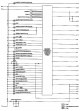


Driver information system — instrument cluster self-diagnosis mode
Operations in self-diagnosis mode 1. Turn the ignition key to position «ON». 2. Turn the ignition key to position «OFF», by switching the odometer/odometer display to...
Operations in self-diagnosis mode 1. Turn the ignition key to position «ON». 2. Turn the ignition key to position «OFF», by switching the odometer/odometer display to...

Driver information system — removing and installing instrument cluster
Attention: When the instrument cluster needs to be replaced, always replace it with a new one*. *: Under «new» refers to an unused instrument cluster that has not been...
Attention: When the instrument cluster needs to be replaced, always replace it with a new one*. *: Under «new» refers to an unused instrument cluster that has not been...

Driver information system — disassembly and assembly of the instrument cluster
1. Front cover; 2. Upper case; 3. Single instrument control unit Disassembly 1. Disengage the latches (7) and separate the top case. 2 Disengage the latches (6) and...
1. Front cover; 2. Upper case; 3. Single instrument control unit Disassembly 1. Disengage the latches (7) and separate the top case. 2 Disengage the latches (6) and...

Information Computer — Component and Connector Locations
1. Instrument cluster M27. 2. Buttons on the steering wheel M502. 3. Fuel level sensor and VZZ fuel pump. 4. Oil level sensor F44: model with HR engine. 5. Ambient...
1. Instrument cluster M27. 2. Buttons on the steering wheel M502. 3. Fuel level sensor and VZZ fuel pump. 4. Oil level sensor F44: model with HR engine. 5. Ambient...

Information Computer — System Description
See your computer's instruction manual. Information computer The computer displays the following options: Odometer reading Odometer A/B Power reserve Average fuel...
See your computer's instruction manual. Information computer The computer displays the following options: Odometer reading Odometer A/B Power reserve Average fuel...
Driver Information System — Warning Lamps — System Description
Low oil pressure warning light Lights up when the engine oil pressure drops below normal. The IPDM E/R module reads the signal from the low oil pressure warning light...
Low oil pressure warning light Lights up when the engine oil pressure drops below normal. The IPDM E/R module reads the signal from the low oil pressure warning light...

Driver Information System — Warning Lamps — Component and Connector Locations
1. Instrument cluster M27. 2. Block IPDM E/R E5, E12. 3. Low oil pressure warning light switch. F23: Models with CR engine F45: Models with HR engine
1. Instrument cluster M27. 2. Block IPDM E/R E5, E12. 3. Low oil pressure warning light switch. F23: Models with CR engine F45: Models with HR engine
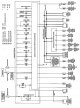

Driver Information System — Horn — Component and Connector Locations
1. Instrument cluster M27. 2. Block BCM M57, M59. 3. M60 smart key block. 4. Combined switch MZ8 5. Ignition lock and ignition lock handle M34 (with smart key). 6....
1. Instrument cluster M27. 2. Block BCM M57, M59. 3. M60 smart key block. 4. Combined switch MZ8 5. Ignition lock and ignition lock handle M34 (with smart key). 6....
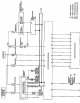
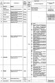
Driver information system — sound alarm — standard voltage values at the contacts of the BCM unit and the contacts of the instrument cluster
Standard voltage values on the contacts of the VSM block (): Without smart key *1: Left hand drive models *2: Right hand drive models Standard voltage values at the...
Standard voltage values on the contacts of the VSM block (): Without smart key *1: Left hand drive models *2: Right hand drive models Standard voltage values at the...

Horn — removal and installation
Removing 1. Remove the grille. See chapter Body . 2. Disconnect the connector from the horn. 3. Loosen the fixing nut (A) and remove the klaxon (1) from the car....
Removing 1. Remove the grille. See chapter Body . 2. Disconnect the connector from the horn. 3. Loosen the fixing nut (A) and remove the klaxon (1) from the car....

Electrical outlet — removal and installation
Removing 1. Remove the center console assembly. See chapter Body . 2. Remove the cover from the dashboard rack. See chapter Body . 3. Disconnect the connector from the...
Removing 1. Remove the center console assembly. See chapter Body . 2. Remove the cover from the dashboard rack. See chapter Body . 3. Disconnect the connector from the...
Removing and installing the electrical outlet in the console
Removing 1. Remove the center console assembly. See chapter Body . 2. Disconnect the connector from the electrical outlet. 3. Take out the inner chuck (2) from the ring...
Removing 1. Remove the center console assembly. See chapter Body . 2. Disconnect the connector from the electrical outlet. 3. Take out the inner chuck (2) from the ring...

Removal and installation of an electrical outlet in the luggage compartment
Removing 1. Remove the lower side trim of the luggage compartment (left). See chapter Body . 2. Disconnect the connector from the electrical outlet. 3. Take out the...
Removing 1. Remove the lower side trim of the luggage compartment (left). See chapter Body . 2. Disconnect the connector from the electrical outlet. 3. Take out the...
Body Control System — BCM (Body Control Module) — System Description
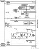
VSM block (body control unit) controls the operation of various electrical units installed on the vehicle. Purpose of the VSM block In addition to the function of...
VSM block (body control unit) controls the operation of various electrical units installed on the vehicle. Purpose of the VSM block In addition to the function of...

Body control system — BCM unit (body control unit) — removal and installation of the BCM unit
Attention: In case of replacement, always replace the BCM with a new one*. Under «new» means a control unit that has not been used and has not been supplied with power...
Attention: In case of replacement, always replace the BCM with a new one*. Under «new» means a control unit that has not been used and has not been supplied with power...
This section is available on: russian, bulgarian, belarusian, ukrainian, serbian, croatian, romanian, polish, slovak, hungarian
Similar information for other Nissan models
➜ Electrical equipment: Equipment and devices Nissan Almera 1 (1995-2000)
➜ Electrical equipment: Equipment and devices Nissan Maxima 4 (1994-1999)
➜ Body and electrical equipment: Equipment and devices Nissan Terrano 1 (1986-1995, petrol)
➜ Electrical equipment: Equipment and devices Nissan Patrol 4 (1987-1997, petrol)
➜ Body and electrical equipment: Equipment and devices Nissan Example 1 (1990-1996, petrol)
➜ Electrical equipment: Equipment and devices Nissan Serena 2 (1999-2005)
➜ Electrical equipment: Equipment and devices Nissan Sunny 7 (1990-1998)
Link in different formats to this section
TEXTHTMLBB Code
- User manual
- Control devices
- Preparing to move
- Starting engine and driving
- Maintenance
- Technical information
- Power unit
- Engine repair CR
- Engine repair HR
- Engine lubrication system
- Cooling system (CR)
- Cooling system (HR)
- Fuel and exhaust system
- Engine management (CR)
- Engine management (HR)
- Transmission
- Clutch
- Mechanical gearbox
- Automatic gearbox
- Drive shafts and axles
- Chassis
- Car suspension
- Brake system
- Steering
- Body
- Airbags (SRS)
- Doors, hood and locks
- Glasses and mirrors
- Exterior (external elements)
- Interior (internal elements)
- Air conditioning automatic
- Electrical equipment
- Equipment and devices
- Launch and charge system
- Headlights and lighting
- Windshield wipers and washers
- General information
- Introduction to guide
- Governing bodies
- Starting engine and driving
- Maintenance
- Power unit
- Engine repair
- Cooling system
- Heating and ventilation
- Power and exhaust system
- Ignition system
- Charge and launch systems
- Transmission
- Mechanical gearbox
- Automatic gearbox
- Clutch
- Drive shafts and hubs
- Chassis
- Brake system
- Car suspension
- Steering
- Body
- Exterior (external elements)
- Interior (internal elements)
- Electrical equipment
- Equipment and devices
- Electrical circuits
NissanBook.ru © 2018–2024 · Mobile version · Articles about Nissan · Sitemap: EN BG BY UA RS HR RO PL SK HU · Feedback · Site search · Bookmark
Almera 1 (N15) · Maxima 4 (A32) · Terrano 1 (petrol) · Patrol 4 (Y60, petrol) · Example 1 (P10, petrol) · Qashqai 1 (J10) · Serena 2 (C24) · Sunny 7 (B13) · Note 1 · Micra 3 (petrol) ·
Almera 1 (N15) · Maxima 4 (A32) · Terrano 1 (petrol) · Patrol 4 (Y60, petrol) · Example 1 (P10, petrol) · Qashqai 1 (J10) · Serena 2 (C24) · Sunny 7 (B13) · Note 1 · Micra 3 (petrol) ·